
Basic Refrigeration & Air Conditioning


History of Refrigeration 
The history of air conditioning dates back to ancient times, when people used to hang wet mats or cloth in doorways to cool the air. However, modern air conditioning as we know it today was first developed in the early 1900s. In 1902, a young engineer named Willis Carrier invented the first modern air conditioning system. Carrier was working for a printing company in Brooklyn, New York, and was trying to solve a problem with humidity affecting the quality of the paper. Carrier's invention used a refrigeration system to cool air and remove moisture, creating a more comfortable and consistent environment for the printing process. The first air conditioning units were large and expensive, and were primarily used in commercial buildings like theaters and department stores. However, as technology improved and costs decreased, air conditioning became more common in homes and automobiles in the mid-20th century. Today, air conditioning is an essential part of modern life, providing comfort and improving indoor air quality in homes, offices, and public buildings around the world. However, the widespread use of air conditioning also contributes to climate change by increasing energy consumption and greenhouse gas emissions, highlighting the need for more sustainable cooling solutions in the future.
Carrier used his invention to improve manufacturing process control in a printing plant. Air was used to blow air through coils filled with cold water.
The air blowing over the cold coils cooled the air thereby the control on the amount of moisture the colder air could hold, was achieved. In turn, the humidity in the room could be controlled. The low heat and humidity helped maintain consistent paper dimensions and ink alignment.
Later, carrier's technology was applied to increase productivity in the workplace, and the Carrier Air Conditioning Company of America ,was formed. 
The first air conditioner and refrigerators employed toxic or flammable gases like  ammonia, methyl chloride and propaen, which could result in fatal accidents when they leaked.
It was only in 1928, that the first chloroflurocarbon gas, Freon was created by Thomas Midgley. Freon is a trademark name owned by DuPont for any Chlorofluorocarbon (CFC), Hydrogenated CFC (HCFC) , or Hydrofluorocarbon  (HFC) refrigerant, the name and number indicating molecular composition (R-11, R-12, R-22 and R-134a). These gases were safer and began to be used in air conditioner 
An early Carrier industrial air conditioner
Commercial refrigeration

Refrigeration is a process of removing heat from a substance or a space to lower its temperature. It is used in a variety of applications, including air conditioning, food preservation, and industrial processes. The process of refrigeration typically involves compressing a refrigerant gas, which raises its temperature and pressure, and then condensing it into a liquid by removing heat. The liquid refrigerant is then passed through an evaporator, where it evaporates and absorbs heat from the surrounding environment, causing the temperature to drop. The cooled gas is then compressed and the cycle starts again. Refrigeration is based on the principles of thermodynamics and is essential for preserving perishable foods, medicines, and other temperature-sensitive products. It is also used in many industrial processes, such as chemical manufacturing and oil refining, to control temperatures and maintain product quality. Refrigeration technology has evolved over time, with advancements in materials, energy efficiency, and environmental impact. Today, there is growing interest in developing more sustainable refrigeration solutions, such as using natural refrigerants like carbon dioxide or ammonia, to reduce greenhouse gas emissions and mitigate the impact of refrigeration on climate change.

Ice harvesting


Ice harvesting in Massachusetts, 1852, showing the railroad line in the background, used to transport the ice.
An 1870 refrigerator car design. Hatches in the roof provided access to the tanks for the storage of harvested ice at each end.
An early example of the consumerization of mechanical refrigeration that began in the early 20th century. The refrigerant was sulfur dioxide

                                                        Vapor compression refrigeration
Refrigeration Cycle 
A simple stylized diagram of the refrigeration cycle: 1) condensing coil, 2) expansion valve, 3) evaporator coil, 4) compressor


Air conditioning is a technology used to control and regulate the temperature, humidity, and air quality in indoor spaces, such as homes, offices, and public buildings. Air conditioning systems work by using a combination of heating, ventilation, and cooling mechanisms to create a comfortable indoor environment. The process of air conditioning typically involves circulating air through a refrigeration cycle, similar to that used in refrigeration. Air is drawn into the system through a filter, where it is cleaned and then passed over a coil containing a cold refrigerant. As the air passes over the cold coil, heat is removed from it and the air is cooled. The cooled air is then circulated back into the space through a system of ducts or vents. In addition to cooling, air conditioning systems can also control humidity levels by removing excess moisture from the air. This is important for maintaining a comfortable indoor environment and preventing issues such as mold growth and damage to furniture and electronics. Air conditioning has become an essential part of modern life, providing comfort and improving indoor air quality in a variety of settings. However, the energy consumption associated with air conditioning can have a significant impact on the environment, contributing to climate change. Therefore, efforts are being made to develop more energy-efficient and sustainable air conditioning technologies.

                 Evaporator, indoor unit, or terminal, side of a ductless split-type air conditioner


An array of air conditioner condenser units outside a commercial office building

Refrigeration
 
Commercial refrigeration

Refrigeration is a process of removing heat from a substance or a space to lower its temperature. It is used in a variety of applications, including air conditioning, food preservation, and industrial processes. The process of refrigeration typically involves compressing a refrigerant gas, which raises its temperature and pressure, and then condensing it into a liquid by removing heat. The liquid refrigerant is then passed through an evaporator, where it evaporates and absorbs heat from the surrounding environment, causing the temperature to drop. The cooled gas is then compressed and the cycle starts again. Refrigeration is based on the principles of thermodynamics and is essential for preserving perishable foods, medicines, and other temperature-sensitive products. It is also used in many industrial processes, such as chemical manufacturing and oil refining, to control temperatures and maintain product quality. Refrigeration technology has evolved over time, with advancements in materials, energy efficiency, and environmental impact. Today, there is growing interest in developing more sustainable refrigeration solutions, such as using natural refrigerants like carbon dioxide or ammonia, to reduce greenhouse gas emissions and mitigate the impact of refrigeration on climate change.

Ice harvesting


Ice harvesting in Massachusetts, 1852, showing the railroad line in the background, used to transport the ice.
An 1870 refrigerator car design. Hatches in the roof provided access to the tanks for the storage of harvested ice at each end.
An early example of the consumerization of mechanical refrigeration that began in the early 20th century. The refrigerant was sulfur dioxide

                                                        Vapor compression refrigeration

Air Conditioning 

Refrigeration Cycle 
A simple stylized diagram of the refrigeration cycle: 1) condensing coil, 2) expansion valve, 3) evaporator coil, 4) compressor


Air conditioning is a technology used to control and regulate the temperature, humidity, and air quality in indoor spaces, such as homes, offices, and public buildings. Air conditioning systems work by using a combination of heating, ventilation, and cooling mechanisms to create a comfortable indoor environment. The process of air conditioning typically involves circulating air through a refrigeration cycle, similar to that used in refrigeration. Air is drawn into the system through a filter, where it is cleaned and then passed over a coil containing a cold refrigerant. As the air passes over the cold coil, heat is removed from it and the air is cooled. The cooled air is then circulated back into the space through a system of ducts or vents. In addition to cooling, air conditioning systems can also control humidity levels by removing excess moisture from the air. This is important for maintaining a comfortable indoor environment and preventing issues such as mold growth and damage to furniture and electronics. Air conditioning has become an essential part of modern life, providing comfort and improving indoor air quality in a variety of settings. However, the energy consumption associated with air conditioning can have a significant impact on the environment, contributing to climate change. Therefore, efforts are being made to develop more energy-efficient and sustainable air conditioning technologies.

                 Evaporator, indoor unit, or terminal, side of a ductless split-type air conditioner


An array of air conditioner condenser units outside a commercial office building

Heat 

A glowing-hot metal bar showing incandescence, the emission of light due to its temperature, is often recognized as a source of heat.

Heat is a form of energy that is transferred from one object or system to another as a result of a temperature difference between them. Heat always flows from hotter to cooler objects, until the temperatures become equal and thermal equilibrium is achieved. The movement of heat is driven by the random motion of molecules in matter, such as atoms, ions, and electrons. When two objects at different temperatures come into contact, the molecules in the hotter object collide with those in the cooler object, transferring energy and raising the temperature of the cooler object. Heat can be generated by a variety of sources, including chemical reactions, electrical currents, nuclear reactions, and gravitational forces. It can also be transmitted through different mechanisms, such as conduction, convection, and radiation. Heat is a fundamental concept in thermodynamics, the branch of physics that studies the behavior of matter and energy in relation to temperature and heat transfer. Understanding the principles of heat and energy transfer is important in a variety of fields, from engineering and materials science to environmental science and meteorology.

Units of Heat 

British Thermal Unit (BTU) :- It is the heat required to raise the temperature of 1 pounde of water by in degree Fahrenheit.

Calorie :- It is the heat required to raise the temperature of 1 gram of water by 1 degree Celsius 

The British thermal unit (BTU or Btu) is a measure of heat, which is a form of energy. It was originally defined as the amount of heat required to raise the temperature of one pound of water by one degree Fahrenheit. It is also part of the United States customary units.[1] The SI unit for energy is the joule (J); one BTU equals about 1,055 J

Sensible Heat


Sensible heat is a type of heat that can be felt or sensed by an object or a system, such as an increase in temperature. It is a form of energy that is transferred between two objects or systems at different temperatures and is associated with the kinetic energy of molecules. When two objects with different temperatures come into contact, heat energy flows from the object with higher temperature to the one with lower temperature. As a result, the temperature of the cooler object increases, and the temperature of the hotter object decreases until they reach thermal equilibrium. Sensible heat is the portion of the heat transfer that results in a change in temperature without changing the state of matter. For example, when you touch a hot stove, the heat you feel is sensible heat. Similarly, when you warm up a room with a heater, the heat you feel is also sensible heat. Sensible heat is an important concept in thermodynamics and is used in many practical applications, such as heating and cooling systems, refrigeration, and industrial processes. It is also used in weather forecasting to describe the temperature changes in the atmosphere.

Latent Heat


Latent heat is a type of heat that is involved in a phase change of matter, such as the melting or boiling of a substance. It is the energy absorbed or released during a change in the state of matter without any change in temperature. During a phase change, such as melting or boiling, heat energy is added or removed from the system, but the temperature of the substance remains constant until the phase change is complete. This is because the heat energy is used to break or form the intermolecular bonds between the particles of the substance, rather than increasing or decreasing their kinetic energy. Latent heat is classified into two types: latent heat of fusion and latent heat of vaporization. Latent heat of fusion is the amount of heat energy required to melt a substance, while latent heat of vaporization is the amount of heat energy required to vaporize a substance. Latent heat is an important concept in thermodynamics and is used in many practical applications, such as refrigeration, air conditioning, and industrial processes. For example, in air conditioning systems, the evaporation of a refrigerant absorbs latent heat, which helps to cool the air. In refrigeration systems, the condensation of a refrigerant releases latent heat, which helps to remove heat from the system.
Simple definition
It is the heat that brings about the change in state of a substance without any change in the temperature.
Heat required to freeze water is called latent heat of fusion 
The heat required to vaporize water is called latent heat of vaporization 
Latent heat of fusion of ice is 80 calories/gram or 144 BTU/lb
Latent heat of vaporization of water is 540 calories / gram or 970 BTU/lb


 Relative Humidity

Hygrometer for domestic use, wet/dry psychrometer type


Relative humidity (RH) is a measure of the amount of moisture present in the air compared to the maximum amount of moisture that the air can hold at a particular temperature, expressed as a percentage. Relative humidity is an important factor in determining the comfort level of an indoor environment. When the relative humidity is high, the air can feel humid and uncomfortable, while low relative humidity can cause dryness and discomfort. In addition, relative humidity affects the rate of evaporation, which can impact the cooling effect of sweat on the skin. The relationship between relative humidity and temperature is important in understanding how to control indoor air quality. As temperature increases, the amount of moisture the air can hold also increases, so relative humidity decreases. Conversely, as temperature decreases, relative humidity increases. For example, if the air temperature is 25°C and the relative humidity is 50%, it means that the air contains half of the maximum amount of moisture it can hold at 25°C. If the temperature drops to 20°C while the amount of moisture in the air remains constant, the relative humidity will increase because the air can hold less moisture at a lower temperature. Maintaining a comfortable relative humidity level is important for human health and well-being, as well as for the preservation of buildings and materials. The recommended range for indoor relative humidity is generally between 30% and 60%.

Humidity Ratio 
Humidity Scale is on Right hand side of chart 

Humidity ratio, also known as specific humidity, is a measure of the actual amount of water vapor present in the air, expressed in units of mass of water vapor per unit mass of dry air. Unlike relative humidity, which is expressed as a percentage of the maximum moisture capacity of air, humidity ratio is an absolute measure of moisture content in the air. Humidity ratio is an important parameter in the fields of HVAC (heating, ventilation, and air conditioning) and meteorology, as it helps to determine the amount of moisture that needs to be added or removed from the air to achieve a desired indoor air quality or weather condition. To calculate the humidity ratio, one needs to know the mass of water vapor and the mass of dry air in a given volume or mass of air. The formula for humidity ratio is: Humidity ratio = Mass of water vapor / Mass of dry air Humidity ratio is typically measured in units of grams of water vapor per kilogram of dry air (g/kg). The value of humidity ratio is directly proportional to the absolute humidity of air, which is the total mass of water vapor present in a given volume of air, and is also related to the dew point temperature, which is the temperature at which water vapor begins to condense into liquid water. Controlling humidity ratio is important in maintaining a comfortable and healthy indoor environment, as high humidity can lead to mold growth and other indoor air quality issues, while low humidity can cause dry skin, irritation, and other health problems.

Comfort Conditions 
Comfort conditions for air conditioners typically refer to the indoor environmental conditions that the air conditioning system is designed to achieve and maintain in order to ensure occupant comfort. These conditions include factors such as temperature, humidity, and air quality. The specific comfort conditions can vary depending on factors like the local climate, building type, occupancy, and cultural preferences. Here are some common comfort conditions for air conditioning systems: Temperature: Air conditioners are designed to maintain indoor air temperatures within a specific range to ensure thermal comfort. Common temperature settings for cooling mode often fall within the range of 72-78°F (22-26°C). However, these settings can be adjusted based on the preferences and needs of the occupants. Humidity: Air conditioners also help control indoor humidity levels. A comfortable relative humidity range is typically between 30% and 60%. Lower humidity helps prevent mold growth and provides a more comfortable indoor environment, especially in hot and humid climates. Air Movement: While not directly controlled by air conditioners, the distribution of cooled air through air vents or ducts helps ensure even temperature distribution and minimizes drafts. Air Quality: Air conditioning systems can play a role in maintaining indoor air quality by filtering out particulates, allergens, and contaminants. This contributes to a healthier and more comfortable indoor environment. The general comfort conditions are DB Temperatures should be 72-78 degree Fahrenheit RH should be 50 to 60 % Air motion across the body should be 15 - 40 Feet per minute
Boyle's law
The mathematical equation for Boyle's law is: P V = k PV=k where P denotes the pressure of the system, V denotes the volume of the gas, k is a constant value representative of the temperature and volume of the system.
Boyle's law is a gas law that describes the inverse relationship between the pressure and volume of a gas, assuming the temperature and mass of the gas are constant. The law is named after the Anglo-Irish scientist Robert Boyle, who first described it in 1662. Boyle's law can be expressed mathematically as: P1V1 = P2V2 Where P1 and V1 are the initial pressure and volume of the gas, and P2 and V2 are the final pressure and volume of the gas, respectively. The law states that if the temperature and mass of a gas are constant, then the product of the pressure and volume of the gas is a constant. This law is important in many fields of science and engineering, including chemistry, physics, and mechanical engineering. It is particularly useful in the design and operation of equipment that involves the compression or expansion of gases, such as refrigeration systems, air compressors, and engines. Boyle's law is often combined with other gas laws, such as Charles' law and the ideal gas law, to describe the behavior of gases in different conditions.
Charles' law
An animation demonstrating the relationship between volume and temperature

Charles's law (also known as the law of volumes) is an experimental gas law that describes how gases tend to expand when heated. A modern statement of Charles's law is:

When the pressure on a sample of a dry gas is held constant, the Kelvin temperature and the volume will be in direct proportion.[1]

This relationship of direct proportion can be written as:

So this means:

where:


Charles' law is a gas law that describes the direct proportional relationship between the temperature and volume of a gas, assuming the pressure and mass of the gas are constant. The law is named after the French physicist Jacques Charles, who first formulated it in 1787. Charles' law can be expressed mathematically as: V1 / T1 = V2 / T2 Where V1 and T1 are the initial volume and temperature of the gas, and V2 and T2 are the final volume and temperature of the gas, respectively. The law states that if the pressure and mass of a gas are constant, then the ratio of the volume to the temperature of the gas is a constant. This law is important in many fields of science and engineering, including chemistry, physics, and mechanical engineering. It is particularly useful in the design and operation of equipment that involves heating or cooling gases, such as air conditioning systems and heat exchangers. Charles' law is often combined with other gas laws, such as Boyle's law and the ideal gas law, to describe the behavior of gases in different conditions.
Gay-Lussac's law
Under STP, a reaction between three cubic meters of hydrogen gas and one cubic meter of nitrogen gas will produce about two cubic meters of ammonia.

Gay-Lussac's law, also known as the pressure-temperature law, is a gas law that describes the direct proportional relationship between the pressure and temperature of a gas, assuming the volume and mass of the gas are constant. The law is named after the French chemist Joseph Louis Gay-Lussac, who first formulated it in 1802. Gay-Lussac's law can be expressed mathematically as: P1 / T1 = P2 / T2 Where P1 and T1 are the initial pressure and temperature of the gas, and P2 and T2 are the final pressure and temperature of the gas, respectively. The law states that if the volume and mass of a gas are constant, then the ratio of the pressure to the temperature of the gas is a constant. This law is important in many fields of science and engineering, including chemistry, physics, and mechanical engineering. It is particularly useful in the design and operation of equipment that involves heating or cooling gases, such as gas turbines and combustion engines. Gay-Lussac's law is often combined with other gas laws, such as Boyle's law and Charles' law, to describe the behavior of gases in different conditions. The combination of these laws is known as the ideal gas law, which provides a comprehensive description of the behavior of gases in a wide range of conditions.

Combined Gas Law

The combined gas law is a gas law that combines the three basic gas laws, namely Boyle's law, Charles's law, and Gay-Lussac's law, into a single expression. It relates the pressure, volume, and temperature of a gas, assuming the amount of gas is constant. The combined gas law is expressed mathematically as: (P1 x V1) / T1 = (P2 x V2) / T2 Where P1, V1, and T1 are the initial pressure, volume, and temperature of the gas, and P2, V2, and T2 are the final pressure, volume, and temperature of the gas, respectively. The ideal gas law is an equation of state that relates the pressure, volume, temperature, and amount of a gas. It is derived from the combined gas law and is expressed mathematically as: PV = nRT Where P is the pressure of the gas, V is its volume, n is the amount of the gas in moles, R is the universal gas constant, and T is the absolute temperature of the gas in Kelvin. The ideal gas law provides a comprehensive description of the behavior of an ideal gas, which is a hypothetical gas that follows the gas laws under all conditions. However, real gases deviate from the ideal gas law at high pressures and low temperatures due to intermolecular forces and the finite size of gas molecules. In such cases, more complex equations of state, such as the van der Waals equation, are used to describe the behavior of

Mode Of Transfer Of Heat

Heat can be transferred from one object or substance to another in three ways: conduction, convection, and radiation. Conduction: Conduction is the transfer of heat through a material or between objects that are in direct contact with each other. In this process, heat is transferred by the collision of molecules or atoms in a material. Metals are good conductors of heat due to the mobility of their free electrons. Convection: Convection is the transfer of heat through a fluid, such as a gas or liquid, due to the movement of the fluid itself. This process involves the transfer of heat by the movement of hot and cold fluids. An example of convection is the circulation of hot air from a radiator or the movement of hot water in a heating system. Radiation: Radiation is the transfer of heat through electromagnetic waves, which can travel through a vacuum. This process does not require a material medium for heat transfer to occur. Examples of radiation include the transfer of heat from the sun to the earth, the warmth you feel from a fire, or the heat transfer in an infrared heater. Understanding these modes of heat transfer is important in designing and optimizing heating and cooling systems, such as air conditioning and refrigeration systems.
Temperature

 Temperature is a measure of the average kinetic energy of the particles in a substance. In simpler terms, it is a measure of how hot or cold something is. Temperature is typically measured using a thermometer, and the most common unit of measurement is degrees Celsius (°C) or degrees Fahrenheit (°F). Temperature plays a fundamental role in many physical and chemical processes, such as the expansion and contraction of materials, the boiling and freezing points of liquids, and the rate of chemical reactions. Temperature also has important effects on living organisms, influencing their metabolic rates, behavior, and growth.

Dry-bulb temperature 

 Dry-bulb temperature, also known as air temperature, is the temperature of air measured by a thermometer that is not affected by moisture. It is a fundamental parameter in meteorology and HVAC (heating, ventilation, and air conditioning) systems, and is typically measured using a standard thermometer placed in a shaded area. Dry-bulb temperature is important because it affects human comfort, as well as the performance of various equipment and systems. For example, the efficiency of an air conditioning system is strongly influenced by the dry-bulb temperature of the air it is trying to cool. Dry-bulb temperature is usually expressed in degrees Celsius (°C) or degrees Fahrenheit (°F).
Wet-Bulb Temperature

 Wet-bulb temperature is the temperature of a surface that is in contact with air that has been cooled to its dew point temperature, usually by evaporating water from a wick or other wetted surface. It is a measure of the lowest temperature that can be achieved through evaporative cooling and is used to determine the relative humidity of the air. Wet-bulb temperature is important in meteorology and HVAC (heating, ventilation, and air conditioning) systems because it can be used to calculate other important parameters such as dew point temperature, relative humidity, and enthalpy. Wet-bulb temperature is usually expressed in degrees Celsius (°C) or degrees Fahrenheit (°F) and is typically measured using a thermometer that is covered with a wet wick or cloth and exposed to moving air.
Dew Point Temperature 

 Dew point temperature is the temperature at which air becomes saturated with water vapor and begins to condense into liquid water. It is the temperature at which the air cannot hold any more moisture in the form of water vapor, and any additional moisture will condense as dew, fog, or precipitation. Dew point temperature is an important parameter in meteorology and HVAC (heating, ventilation, and air conditioning) systems because it can be used to determine the relative humidity of the air. When the air temperature is equal to the dew point temperature, the relative humidity is 100%. Dew point temperature is usually expressed in degrees Celsius (°C) or degrees Fahrenheit (°F) and can be measured using a hygrometer or calculated using the wet-bulb temperature and dry-bulb temperature of the air.

Enthalpy 


 In HVAC (heating, ventilation, and air conditioning) systems, enthalpy is a measure of the total heat content of the air, including both its sensible heat (related to temperature) and its latent heat (related to moisture content). Enthalpy is used to describe the total amount of energy that must be added or removed from the air to achieve a desired temperature and humidity level.

In HVAC systems, enthalpy is typically measured in terms of the amount of heat required to raise the temperature of a certain mass of air by one degree Celsius or Fahrenheit, and is expressed in units of joules per kilogram (J/kg) or British thermal units per pound (BTU/lb). The enthalpy of air can be calculated using the dry-bulb temperature, wet-bulb temperature, and barometric pressure, or it can be measured directly using specialized instruments known as enthalpy wheels or heat exchangers.

Enthalpy is an important parameter in HVAC design and operation because it can be used to determine the energy required to heat or cool a space and to calculate the performance of HVAC equipment such as air conditioners, heat pumps, and humidifiers. By controlling the enthalpy of the air, HVAC systems can maintain comfortable indoor conditions while minimizing energy consumption and operating costs


Boiling Point


 Boiling point is the temperature at which the vapor pressure of a liquid equals the pressure exerted on the liquid by its surroundings. At the boiling point, the liquid starts to boil and evaporate, changing its state from liquid to gas. The boiling point of a substance is determined by factors such as the pressure and composition of its surroundings, as well as its own molecular structure.

The boiling point of a substance is typically measured at standard pressure, which is 1 atmosphere (atm) or 101.325 kilopascals (kPa). The boiling point of water at standard pressure is 100°C (212°F), which means that water will boil and evaporate when its temperature reaches 100°C at sea level. However, the boiling point of a substance can vary depending on the pressure and altitude of the location where it is being heated. For example, the boiling point of water decreases at higher altitudes because the atmospheric pressure is lower, and water requires less energy to boil.

Boiling point is an important physical property of a substance, as it is used in many applications, such as cooking, distillation, and industrial processes. The boiling point of a substance can also be used to determine its purity, as impurities can raise or lower the boiling point of a substance.

Vapor


 Vapor is the gaseous phase of a substance that is normally a liquid or a solid at room temperature and atmospheric pressure. When a liquid or a solid is heated, its molecules gain kinetic energy and start to move faster, eventually breaking free from the intermolecular forces holding them together. As the molecules escape into the surrounding environment, they form a vapor.

Vapor can be formed by many substances, such as water, alcohol, and gasoline. It is a natural part of many physical and chemical processes, including boiling, evaporation, and sublimation. Vapor is also an important component of the Earth's atmosphere, where it plays a critical role in the water cycle and the greenhouse effect.

The properties of vapor depend on the properties of the substance from which it is formed, as well as the temperature and pressure of the surrounding environment. For example, the vapor pressure of a substance is the pressure exerted by its vapor when it is in equilibrium with its liquid or solid phase at a given temperature. The boiling point of a substance is the temperature at which its vapor pressure equals the atmospheric pressure, and it starts to boil and evaporate.

Vapor can be controlled and utilized in many applications, such as in steam turbines for electricity generation, in vapor-compression refrigeration systems for cooling, and in industrial processes for drying and separation. However, it can also be hazardous in certain situations, such as in the form of toxic or flammable gases.

Pressure 


 Pressure is a measure of the force per unit area that is exerted by a gas or a liquid on the walls of a container or on a surface. Pressure can be thought of as the intensity or strength of a force that is distributed over an area, and it is typically measured in units of pascals (Pa), atmospheres (atm), or pounds per square inch (psi).

Pressure can be caused by many factors, such as gravity, temperature, and motion of molecules. In gases, pressure arises from the collisions of molecules with each other and with the walls of the container. In liquids, pressure arises from the weight of the liquid and the forces between the molecules. The pressure of a gas or a liquid can change with changes in volume, temperature, or the amount of substance present.

Pressure is an important physical property that has many applications in science and engineering. It is used to measure and control many processes, such as in hydraulic systems, pneumatic systems, and fluid dynamics. Pressure is also used in meteorology to measure atmospheric pressure, which is an important factor in weather forecasting. In addition, pressure is used in medical applications to measure blood pressure and to deliver drugs and fluids into the body.

Vacuum


 Vacuum is a state of very low pressure, in which the pressure is significantly lower than the atmospheric pressure at sea level (which is about 101 kPa or 14.7 psi). In other words, vacuum is a space that contains no or very few particles of matter, such as gas molecules or atoms.

Vacuum can be created by removing air or other gases from a sealed container, using devices such as vacuum pumps. As the pressure inside the container decreases, the density of particles also decreases, and eventually, a vacuum is created. The degree of vacuum is usually measured in units of pressure, such as millimeters of mercury (mmHg) or pascals (Pa).

Vacuum has many important applications in science, engineering, and industry. For example, vacuum is used in the production of electronic components, such as vacuum tubes and semiconductors, to prevent contamination by air or other gases. Vacuum is also used in the production of thin films, such as in the manufacture of computer chips and solar cells. In addition, vacuum is used in space technology, where the absence of air allows spacecraft to operate without the resistance and heating caused by air friction. Vacuum is also used in laboratory experiments and scientific research, such as in the study of the behavior of gases and the properties of materials under extreme conditions

A ton of refrigeration.


 A ton of refrigeration (TR) is a unit of cooling capacity commonly used in the field of refrigeration, air conditioning, and heating. It represents the amount of heat energy that needs to be removed from a substance to change its state from a liquid to a vapor at a given temperature.

One ton of refrigeration is equal to the amount of heat energy that is required to melt one ton of ice (about 907 kg) in a 24-hour period, which is equivalent to 12,000 British Thermal Units (BTUs) per hour, or approximately 3.5 kilowatts of cooling power.

The cooling capacity of a refrigeration system is usually measured in tons of refrigeration, and it depends on factors such as the size of the system, the type of refrigerant used, and the operating conditions. The cooling capacity of a system is important for determining the size and number of components needed to effectively cool a given space or process.

In HVAC and refrigeration systems, the term "ton" is used to indicate the cooling capacity of the system, and it is not related to the weight of the system or its components. So, for example, a 2-ton air conditioning system does not weigh 2 tons, but it has the cooling capacity equivalent to removing the heat generated by melting 2 tons of ice in a 24-hour period.

Electrical power


 Electrical power refers to the rate at which electrical energy is transferred or used. It is measured in watts (W) and is calculated by multiplying the voltage (V) by the current (I) flowing through a circuit. The formula for calculating electrical power is:

Power (P) = Voltage (V) x Current (I)

The unit of electrical power is the watt, which is equal to one joule per second (J/s). One kilowatt (kW) is equal to 1,000 watts.

In electrical systems, power is typically generated by a power plant or generator and is distributed through power lines to homes, businesses, and other buildings. Electrical power is used to operate electrical devices such as lights, appliances, and electronics. The amount of power consumed by a device is measured in kilowatt-hours (kWh), which is equal to the power consumed (in kW) multiplied by the time (in hours) the device is in use.

Atmospheric Pressure


 Atmospheric pressure is the force exerted by the weight of the atmosphere on the Earth's surface and any objects within it. The pressure is caused by the weight of the air molecules above a particular point. The atmospheric pressure at sea level is typically around 1013.25 millibars (or hectopascals), which is equivalent to 14.7 pounds per square inch (psi) or 29.92 inches of mercury (inHg).

Atmospheric pressure changes with altitude, decreasing as you move higher above the Earth's surface. This is because there is less air above you at higher altitudes, and therefore less weight and pressure exerted by the atmosphere.

Changes in atmospheric pressure can also be caused by weather patterns such as high and low-pressure systems. A high-pressure system is characterized by sinking air, which leads to clear skies and fair weather. A low-pressure system is characterized by rising air, which can lead to cloud formation and precipitation.

Atmospheric pressure is measured using a barometer, which can be either a mercury barometer or an aneroid barometer. Mercury barometers use the height of a column of mercury to determine atmospheric pressure, while aneroid barometers use a flexible metal capsule to measure pressure changes.

 Absolute Pressure 


 absolute pressure is the total pressure exerted by a fluid, including atmospheric pressure, measured relative to a perfect vacuum. It is the sum of the gauge pressure and the atmospheric pressure, which is typically around 14.7 pounds per square inch (psi) at sea level. In other words, absolute pressure is the pressure of a fluid relative to an absolute reference point, rather than relative to the local atmospheric pressure. Absolute pressure is commonly used in engineering and physics calculations, particularly in fluid mechanics and thermodynamics. The most common unit for measuring absolute pressure is the pascal (Pa), but other units like pounds per square inch (psi) or bars are also used
Vapor Compression Refrigeration

 The vapor compression refrigeration cycle works by using a refrigerant to absorb heat from a low-temperature environment and transfer it to a high-temperature environment. The cycle consists of four main components: a compressor, a condenser, an expansion valve, and an evaporator.

  1. Compression: The cycle starts with the compressor, which takes in a low-pressure, low-temperature refrigerant gas from the evaporator and compresses it to a high-pressure, high-temperature gas. The compression process increases the refrigerant's temperature and pressure, making it easier for it to release heat in the next step.

  2. Condensation: The high-pressure, high-temperature gas then flows into the condenser, where it releases heat to the surroundings and condenses into a high-pressure, low-temperature liquid. This step is typically done with the help of a fan or other type of heat exchanger that allows the refrigerant to release heat to the outside environment.

  3. Expansion: The liquid refrigerant then flows through an expansion valve, which reduces its pressure and temperature. As the pressure drops, some of the liquid evaporates into a low-pressure, low-temperature gas.

  4. Evaporation: The low-pressure gas then flows into the evaporator, where it absorbs heat from the surrounding environment and fully evaporates into a low-pressure, low-temperature gas. This step is typically done using a fan or other type of heat exchanger that allows the refrigerant to absorb heat from the environment being cooled.

After the gas has completed the evaporation process in the evaporator, it flows back into the compressor to start the cycle again. Overall, the vapor compression refrigeration cycle is an efficient and reliable way to transfer heat and maintain a cool environment in a variety of settings, from residential air conditioning to industrial refrigeration.

BEE Star Rating For Air Conditioners


 BEE star rating for air conditioners is a measure of the energy efficiency of an air conditioning unit. BEE stands for Bureau of Energy Efficiency, which is an Indian government agency that promotes energy conservation and efficiency. The BEE star rating system ranges from 1 to 5 stars, with 5 stars indicating the highest energy efficiency and 1 star indicating the lowest energy efficiency.

The BEE star rating for air conditioners is based on the Energy Efficiency Ratio (EER), which is the ratio of the cooling capacity of the air conditioner to the power consumed by it. A higher EER indicates better energy efficiency and thus a higher BEE star rating. The BEE star rating system also takes into account other factors such as the type of refrigerant used, the cooling capacity of the air conditioner, and the size of the room it is meant to cool.

Air conditioners with higher BEE star ratings are more energy efficient and can help reduce electricity bills while also reducing greenhouse gas emissions. In India, it is mandatory for air conditioner manufacturers to display the BEE star rating label on their products, which helps consumers make informed choices while purchasing air conditioners

An air conditioner compressor


 An air conditioner compressor is a critical component of an air conditioning system that is responsible for circulating the refrigerant through the system and compressing it to increase its temperature and pressure.

The compressor is located in the outdoor unit of a split-system air conditioner or in a window air conditioning unit. It is typically a cylindrical or rectangular shaped unit with a motor, a compressor pump, and a heat exchanger.

When the air conditioning system is turned on, the compressor pump draws in low-pressure, low-temperature refrigerant gas from the evaporator and compresses it into a high-pressure, high-temperature gas. The compressed gas then flows through a series of coils in the condenser where it releases heat to the surrounding environment and condenses into a high-pressure, low-temperature liquid.

The liquid refrigerant then flows through an expansion valve, where it is allowed to expand and cool down before flowing back into the evaporator. This process of compression, condensation, expansion, and evaporation is repeated continuously to maintain a cool and comfortable environment.

The compressor is an essential part of the air conditioning system and plays a crucial role in ensuring the proper functioning of the system. If the compressor is not working correctly, the air conditioner will not be able to cool the room efficiently, and it may require repair or replacement.

Reciprocating Compressor 


A reciprocating compressor is a type of positive displacement compressor that uses reciprocating motion to compress gas or air. The compressor consists of a cylinder, piston, and a suction and discharge valve.

During the suction stroke, the piston moves away from the cylinder head, creating a low-pressure area that draws in gas or air through the suction valve. As the piston moves back towards the cylinder head during the compression stroke, the gas or air is compressed, and its pressure and temperature increase. Finally, during the discharge stroke, the compressed gas or air is pushed out of the cylinder through the discharge valve.

Reciprocating compressors are commonly used in a variety of applications, including refrigeration and air conditioning systems, gas pipelines, and industrial processes. They are known for their high efficiency and reliability, and they can handle a wide range of operating conditions and gas compositions.

However, reciprocating compressors can be relatively noisy and require regular maintenance to ensure optimal performance. In addition, they may not be suitable for applications that require high flow rates or that involve gases with high molecular weights or low vapor pressures.

Rotary vane compressors


 Rotary vane compressors are commonly used in HVAC (Heating, Ventilation, and Air Conditioning) systems as a type of positive displacement compressor to compress refrigerant gas in the refrigeration cycle.

In HVAC systems, rotary vane compressors are typically used in smaller and medium-sized air conditioning and refrigeration units, including window units, split-system air conditioners, and heat pumps. They are preferred in these applications due to their high efficiency, low noise, and compact size.

In a typical HVAC system that uses a rotary vane compressor, the compressor is located in the outdoor unit and is driven by an electric motor. As the rotor with vanes rotates, the vanes slide in and out of the rotor slots, creating expanding and contracting chambers that compress the refrigerant gas.

The compressed gas then flows through the condenser coils, where it releases heat to the surrounding environment and condenses into a high-pressure, high-temperature liquid. The liquid refrigerant then flows through an expansion valve, where it is allowed to expand and cool down before flowing back into the evaporator.

Overall, rotary vane compressors are an important component in HVAC systems, providing efficient and reliable compression of refrigerant gas in air conditioning and refrigeration applications.

Scroll Compressors


 A scroll compressor is a type of positive displacement compressor that is commonly used in HVAC (Heating, Ventilation, and Air Conditioning) systems to compress refrigerant gas in the refrigeration cycle.

In HVAC systems, scroll compressors are typically used in larger air conditioning and refrigeration units, including commercial and industrial HVAC systems. They are preferred in these applications due to their high efficiency, low noise, and reduced vibration compared to other compressor types.

The scroll compressor consists of two interlocking spiral scrolls or plates, one stationary and one orbiting. As the orbiting scroll rotates around the stationary scroll, it creates pockets or chambers between the two scrolls that progressively decrease in size, compressing the refrigerant gas in the process.

The compressed gas then flows through the condenser coils, where it releases heat to the surrounding environment and condenses into a high-pressure, high-temperature liquid. The liquid refrigerant then flows through an expansion valve, where it is allowed to expand and cool down before flowing back into the evaporator.

Overall, scroll compressors are an important component in HVAC systems, providing efficient and reliable compression of refrigerant gas in air conditioning and refrigeration applications. They are known for their high efficiency, low noise, and reduced vibration, making them a popular choice for commercial and industrial HVAC systems where performance and reliability are critical.

Screw Compressor


 An HVAC screw compressor is a type of positive displacement compressor that is commonly used in HVAC (Heating, Ventilation, and Air Conditioning) systems to compress refrigerant gas in the refrigeration cycle.

In HVAC systems, screw compressors are typically used in larger air conditioning and refrigeration units, including commercial and industrial HVAC systems. They are preferred in these applications due to their high capacity, efficiency, and reliability.

The screw compressor consists of two rotating helical screws, one male and one female, that mesh together to compress the refrigerant gas. As the male screw rotates, it forces the refrigerant gas through the screw threads, compressing the gas and increasing its pressure.

The compressed gas then flows through the condenser coils, where it releases heat to the surrounding environment and condenses into a high-pressure, high-temperature liquid. The liquid refrigerant then flows through an expansion valve, where it is allowed to expand and cool down before flowing back into the evaporator.

Overall, screw compressors are an important component in HVAC systems, providing high capacity, efficiency, and reliability for air conditioning and refrigeration applications in commercial and industrial settings. They are known for their high volumetric efficiency, low noise, and reduced vibration, making them a popular choice for larger HVAC systems where performance and reliability are critical.

Centrifugal Compressors


 An HVAC centrifugal compressor is a type of dynamic compressor that is commonly used in large commercial and industrial HVAC (Heating, Ventilation, and Air Conditioning) systems to compress refrigerant gas in the refrigeration cycle.

In HVAC systems, centrifugal compressors are typically used in very large air conditioning and refrigeration units, including large commercial buildings, hospitals, and industrial facilities. They are preferred in these applications due to their high capacity, efficiency, and ability to handle variable loads.

The centrifugal compressor works by using a spinning impeller to accelerate the refrigerant gas and convert its kinetic energy into potential energy, increasing its pressure. The impeller is housed in a stationary casing that directs the gas flow into a diffuser, which slows the flow down and further increases the gas pressure.

The compressed gas then flows through the condenser coils, where it releases heat to the surrounding environment and condenses into a high-pressure, high-temperature liquid. The liquid refrigerant then flows through an expansion valve, where it is allowed to expand and cool down before flowing back into the evaporator.

Overall, centrifugal compressors are an important component in large HVAC systems, providing high capacity, efficiency, and reliability for air conditioning and refrigeration applications in commercial and industrial settings. They are known for their ability to handle variable loads and provide precise control over the refrigeration process, making them a popular choice for large HVAC systems where performance and reliability are critical.

Reciprocating Compressor


 In a reciprocating compressor, the piston is a component that is responsible for compressing the refrigerant gas by reciprocating or moving back and forth inside a cylinder. The piston is typically made of a durable material such as steel or aluminum and is designed to withstand high pressures and temperatures.

The piston is connected to a crankshaft through a connecting rod, which converts the reciprocating motion of the piston into rotational motion of the crankshaft. As the piston moves back and forth, it creates a suction or low-pressure area in the cylinder on the intake stroke, which draws refrigerant gas into the cylinder. On the compression stroke, the piston moves up and compresses the gas, increasing its pressure and temperature.

The piston is typically fitted with piston rings, which help to seal the cylinder and prevent refrigerant gas from leaking past the piston. The piston rings also help to reduce friction between the piston and the cylinder walls, ensuring smooth operation of the compressor.

Overall, the piston is a critical component of a reciprocating compressor, responsible for compressing the refrigerant gas and ensuring efficient and reliable operation of the compressor. The design and materials used for the piston must be carefully chosen to ensure that it can withstand the high pressures and temperatures involved in the compression process and operate smoothly over a long period of time.

Crankshaft


 In a reciprocating compressor, the crankshaft is a component that converts the reciprocating motion of the piston into the rotational motion required to drive the compressor. The crankshaft is typically made of a durable material such as steel and is designed to withstand high stresses and forces.

The crankshaft is connected to the piston through a connecting rod, which converts the linear motion of the piston into rotational motion of the crankshaft. As the piston moves back and forth inside the cylinder, the connecting rod transfers this motion to the crankshaft, which rotates as a result.

The crankshaft is typically supported by bearings, which allow it to rotate smoothly and reduce friction between the rotating components. The bearings are usually lubricated to reduce wear and ensure smooth operation of the compressor.

The crankshaft is also typically connected to a drive motor or engine, which provides the power required to rotate the crankshaft and drive the compressor. The speed of the crankshaft can be controlled by adjusting the speed of the drive motor or engine, allowing for precise control over the compression process.

Overall, the crankshaft is a critical component of a reciprocating compressor, responsible for converting the reciprocating motion of the piston into the rotational motion required to drive the compressor. The design and materials used for the crankshaft must be carefully chosen to ensure that it can withstand the high stresses and forces involved in the compression process and operate smoothly over a long period of time.

Connecting Rod 

 In a reciprocating compressor, the connecting rod is a component that connects the piston to the crankshaft, transferring the reciprocating motion of the piston into the rotational motion of the crankshaft. The connecting rod is typically made of a strong and durable material, such as steel, and is designed to withstand high stresses and forces.

The connecting rod is attached to the piston at one end and to the crankshaft at the other end. As the piston moves back and forth inside the cylinder, the connecting rod transfers this motion to the crankshaft, which rotates as a result. The motion of the connecting rod is complex and involves both rotational and translational movement, which requires careful design and construction to ensure that it operates smoothly and efficiently.

The connecting rod is typically fitted with bearings at both ends, which allow it to rotate and pivot smoothly and reduce friction between the moving components. The bearings are usually lubricated to reduce wear and ensure smooth operation of the compressor.

Overall, the connecting rod is a critical component of a reciprocating compressor, responsible for transferring the reciprocating motion of the piston into the rotational motion of the crankshaft. The design and materials used for the connecting rod must be carefully chosen to ensure that it can withstand the high stresses and forces involved in the compression process and operate smoothly over a long period of time.

Valve Plate


 In a reciprocating compressor, the valve plate is a component that controls the flow of refrigerant gas in and out of the cylinder. The valve plate is typically made of a durable material such as steel or aluminum and is designed to withstand high pressures and temperatures.

The valve plate is located at the top of the cylinder and is held in place by screws or bolts. It contains a series of suction and discharge valves, which are responsible for controlling the flow of refrigerant gas into and out of the cylinder.

During the suction stroke, the suction valves open, allowing refrigerant gas to flow into the cylinder from the evaporator. During the compression stroke, the discharge valves open, allowing the compressed refrigerant gas to flow out of the cylinder and into the condenser.

The valve plate is typically fitted with valve reeds, which help to ensure that the valves open and close smoothly and prevent refrigerant gas from leaking past the valves. The valve reeds are usually made of a flexible material such as stainless steel and are designed to flex as the valves open and close.

Overall, the valve plate is a critical component of a reciprocating compressor, responsible for controlling the flow of refrigerant gas in and out of the cylinder and ensuring efficient and reliable operation of the compressor. The design and materials used for the valve plate must be carefully chosen to ensure that it can withstand the high pressures and temperatures involved in the compression process and operate smoothly over a long period of time.

Sleeve Bearing


 A sleeve bearing also known as a journal bearing, is a type of bearing that supports a rotating shaft or journal in a machine or mechanical system. It consists of a cylindrical sleeve, usually made of a low-friction material such as bronze or plastic, that surrounds the rotating shaft.

The sleeve bearing works by creating a thin film of lubricating oil or grease between the shaft and the sleeve. As the shaft rotates, it creates a hydrodynamic pressure that lifts the shaft slightly off the bearing surface, reducing friction and wear. The lubricating oil or grease also helps to dissipate heat generated by the friction between the shaft and the bearing.

Sleeve bearings are commonly used in many types of machinery, including electric motors, pumps, and compressors, where they provide reliable and cost-effective support for rotating shafts. They are typically less expensive than other types of bearings, such as ball bearings, and can handle higher loads and speeds in some applications.

However, sleeve bearings also have some disadvantages. They require a continuous supply of lubricating oil or grease to operate effectively, and the lubricant can become contaminated or break down over time, leading to increased wear and failure of the bearing. Additionally, sleeve bearings can generate more heat than other types of bearings due to the friction between the shaft and the bearing surface.


Insert Bearing 


 An insert bearing is a type of rolling-element bearing that is designed to be inserted into a housing or mounted directly onto a shaft. Also known as a mounted bearing or pillow block bearing, it typically consists of an inner ring with an extended outer race, a set of rolling elements, and an outer ring with a mounting surface.

Insert bearings are commonly used in a variety of industrial applications, including conveyors, food processing equipment, and agricultural machinery. They are designed to provide reliable support for rotating shafts and can be easily mounted and replaced when necessary.

One of the key advantages of insert bearings is their versatility. They are available in a wide range of sizes and configurations, making it easy to find the right bearing for a particular application. They are also available in different materials, including steel, stainless steel, and plastic, depending on the requirements of the application.

Insert bearings can be mounted in a variety of ways, including with set screws, eccentric locking collars, or adapter sleeves. Set screw mounting is the most common method and involves tightening one or more screws against the shaft to secure the bearing in place. Eccentric locking collars and adapter sleeves are alternative methods that allow for easier installation and adjustment.

Overall, insert bearings are a reliable and cost-effective solution for supporting rotating shafts in a wide range of industrial applications. They are easy to install and maintain, and are available in a variety of sizes and configurations to meet the needs of different applications.

Shaft  Seal 


 A shaft seal in an open type compressor is a component that is used to prevent refrigerant gas from leaking out of the compressor and into the surrounding environment. The shaft seal is typically located on the shaft of the compressor and is designed to create a tight seal between the rotating shaft and the compressor housing.

There are several types of shaft seals that can be used in open type compressors, including lip seals, mechanical seals, and labyrinth seals. Lip seals are the most common type of shaft seal and consist of a flexible lip that contacts the shaft and creates a tight seal. Mechanical seals, on the other hand, use a series of springs and mechanical components to create a tight seal. Labyrinth seals are a more complex type of seal that use a series of closely spaced fins or baffles to create a tortuous path for the refrigerant gas, preventing it from leaking out of the compressor.

The type of shaft seal used in an open type compressor will depend on several factors, including the type of refrigerant gas being used, the operating conditions of the compressor, and the requirements of the application. Some compressors may require a high-performance shaft seal that can handle high pressures and temperatures, while others may require a more basic seal that is designed for low-cost applications.

Overall, the shaft seal is an important component of an open type compressor, responsible for preventing refrigerant gas from leaking out of the compressor and ensuring efficient and reliable operation. The design and materials used for the shaft seal must be carefully chosen to ensure that it can withstand the operating conditions of the compressor and provide reliable performance over a long period of time.

Air-cool condenser


 An HVAC (Heating, Ventilation, and Air Conditioning) system typically includes an air-cooled condenser as one of its key components. The condenser is responsible for releasing the heat that has been absorbed by the refrigerant as it circulated through the system.

An air-cooled condenser works by using a fan to blow air over a coil containing the hot refrigerant. As the air flows over the coil, it absorbs the heat from the refrigerant and carries it away. The cooled refrigerant then flows back into the system to repeat the process.

Air-cooled condensers are typically used in smaller HVAC systems, such as those found in residential or small commercial buildings. They are less expensive and easier to install than water-cooled condensers, which require a separate water supply and drainage system.

However, air-cooled condensers are generally less efficient than water-cooled condensers, particularly in hot weather. This is because the ambient air temperature affects the cooling capacity of the condenser, and in hot weather, the air may not be cool enough to effectively remove the heat from the refrigerant. As a result, air-cooled systems may consume more energy and have a lower overall cooling capacity than water-cooled systems.

Natural Draft Condenser


 The condenser in a refrigerator is a heat exchanger that is responsible for removing heat from the refrigerant and releasing it into the surrounding environment. The condenser is typically located on the back or bottom of the refrigerator, and it consists of a coil of tubing and a fan.

When the refrigerant flows through the condenser, it gives up heat to the surrounding air or water, depending on the type of condenser. This causes the refrigerant to condense back into a liquid form, and it is then sent back to the evaporator to begin the cooling cycle again.

There are two main types of condensers used in refrigerators: air-cooled and water-cooled. Air-cooled condensers use a fan to blow air over the coil of tubing, while water-cooled condensers use water to remove heat from the refrigerant. Air-cooled condensers are the most common type used in household refrigerators, as they are simpler and less expensive than water-cooled condensers.

To keep the condenser working efficiently, it is important to keep it clean and free of debris. Over time, dust and other particles can accumulate on the condenser coil, which can reduce its ability to transfer heat. Regular cleaning with a vacuum or brush can help to maintain the efficiency of the condenser and prolong the life of the refrigerator.

Forced Draft Condenser


 A forced draft condenser is a type of heat exchanger used in industrial applications to remove heat from a process or system. It is called "forced draft" because it uses a fan or blower to force air through the condenser, rather than relying on natural draft or buoyancy.

The forced draft condenser consists of a large steel shell with a bundle of tubes running through it, similar to the natural draft condenser. However, instead of relying on the natural buoyancy of hot gases, a fan or blower is used to create a high-velocity flow of air over the tubes, which increases the heat transfer rate and improves efficiency.

Forced draft condensers are commonly used in power plants, refineries, and other large-scale industrial applications where high heat transfer rates and efficient cooling are required. They are typically designed for high flow rates and high heat transfer rates, and they can operate over a wide range of temperatures and pressures.

The advantage of a forced draft condenser is that it can be designed to meet specific performance requirements, and it can be more efficient than a natural draft condenser. However, it is also more complex and expensive, as it requires a fan or blower to be installed and maintained.

In HVAC systems, forced draft air-cooled condensers are often used to remove heat from the refrigerant. These systems typically use a fan to blow air over the condenser coil, which removes heat from the refrigerant and cools it back to a liquid state.

Water-Cooled Condenser


 A water-cooled condenser is a type of heat exchanger used in air conditioning, refrigeration, and other cooling systems to remove heat from the refrigerant. Unlike an air-cooled condenser, which uses air as the cooling medium, a water-cooled condenser uses water.

The water-cooled condenser typically consists of a shell-and-tube heat exchanger, with the refrigerant flowing through the tubes and the cooling water flowing through the shell. As the refrigerant flows through the tubes, it gives up heat to the cooling water, which absorbs the heat and carries it away.

The cooling water can be sourced from a variety of places, such as a cooling tower, a river, a lake, or a well. Once the water has absorbed the heat from the refrigerant, it is typically discharged back into the environment at a slightly elevated temperature.

Water-cooled condensers are typically more efficient than air-cooled condensers, as water has a higher heat transfer coefficient than air. However, they are also more expensive to install and maintain, as they require a constant supply of water and a separate water treatment system to prevent scale and corrosion.

In some cases, water-cooled condensers are required by local codes or regulations, such as in urban areas where there may be restrictions on the use of air-cooled equipment due to noise or environmental concerns.

Evaporator


 In an air conditioner, the evaporator is a key component that is responsible for cooling the indoor air. The evaporator is located inside the indoor unit of the air conditioner and is made up of a coil of tubing that is filled with a refrigerant.

The basic function of the evaporator in an air conditioner is to absorb heat from the indoor air that is blown over it by the blower fan. As the refrigerant inside the coil absorbs heat, it evaporates into a gas, and this process causes the temperature of the coil to drop.

The cooled air is then blown back into the indoor space by the blower fan, reducing the temperature and humidity levels inside the room. The refrigerant gas is then transported to the outdoor unit of the air conditioner, where it is compressed, and the heat absorbed by the evaporator is released to the outdoor air.

There are different types of evaporators used in air conditioners, including the following:

  1. Finned tube evaporator: This is the most common type of evaporator used in air conditioners. It is made up of a coil of copper tubing with aluminum fins attached to it. The fins increase the surface area of the coil, allowing it to absorb more heat from the air.

  2. Plate and fin evaporator: This type of evaporator is made up of a series of plates with fins attached to them. The refrigerant flows through the narrow passages between the plates, and the air is blown over the fins to cool the refrigerant.

  3. Shell and tube evaporator: This type of evaporator consists of a shell filled with refrigerant and a series of tubes through which the warm air flows. The refrigerant absorbs heat from the warm air as it passes through the tubes.

The efficiency and effectiveness of the evaporator in an air conditioner have a significant impact on the overall cooling performance of the unit. Regular maintenance and cleaning of the evaporator coil can help to ensure optimal performance and energy efficiency of the air conditioner.

Drear


 In an air conditioner, the drier is a component that is designed to remove moisture from the refrigerant before it enters the compressor. The drier is typically located between the evaporator and the compressor in the refrigerant circuit.

The primary function of the drier in an air conditioner is to protect the compressor from moisture and contaminants that can damage the compressor and reduce its lifespan. Moisture can cause corrosion of the compressor and other components in the refrigerant circuit, and can also form ice inside the air conditioning system, which can lead to reduced efficiency and cooling capacity.

The drier works by using a desiccant material, such as silica gel or activated alumina, to absorb moisture from the refrigerant. As the refrigerant passes through the drier, the desiccant material removes any moisture that is present in the refrigerant.

In addition to removing moisture, the drier also helps to remove other contaminants, such as dirt and debris, from the refrigerant. This helps to protect the compressor and other components in the refrigerant circuit from damage and ensures optimal performance of the air conditioning system.

Over time, the desiccant material in the drier can become saturated with moisture and contaminants, reducing its effectiveness. Therefore, it is important to replace the drier periodically as part of the air conditioning system's regular maintenance. The frequency of drier replacement will depend on the specific system and operating conditions, and should be determined by a qualified HVAC technician.

Air Filter


 An air filter is an essential component in an air conditioner that helps to maintain indoor air quality by removing airborne particles such as dust, pollen, and other contaminants from the air. The air filter is typically located in the air handler of the indoor unit of the air conditioner.

The primary function of an air filter in an air conditioner is to protect the air conditioning system components, including the evaporator coil, from dirt and debris that can reduce system efficiency and performance. A clean air filter helps to maintain proper airflow, which is essential for efficient cooling and dehumidification of the indoor space.

There are several types of air filters used in air conditioners, including:

  1. Fiberglass filters: These are the most basic and inexpensive type of air filter. They are made of spun fiberglass and are disposable. They are designed to capture large particles such as dust and dirt, but are not very effective at capturing smaller particles such as pollen and mold spores.

  2. Pleated filters: These filters are made of folded paper or synthetic materials and are more effective at capturing smaller particles than fiberglass filters. They are also disposable and need to be replaced periodically.

  3. High-efficiency particulate air (HEPA) filters: These filters are made of dense mesh materials that are capable of capturing particles as small as 0.3 microns. They are highly effective at removing allergens and other contaminants from the air, but are also more expensive than other types of filters.

It is important to clean or replace the air filter in an air conditioner on a regular basis to maintain optimal performance and indoor air quality. The frequency of filter cleaning or replacement will depend on several factors, including the type of filter, the level of use, and the indoor air quality. A qualified HVAC technician can recommend the appropriate air filter and maintenance schedule for a specific air conditioning system.

Capillary tube


 The capillary tube is a component in an air conditioning system that is responsible for controlling the flow of refrigerant from the high-pressure side to the low-pressure side of the system. The capillary tube is a small diameter copper tube that is usually between 0.5 mm to 1.5 mm in diameter, and several feet in length. It is located between the condenser and evaporator in the refrigerant circuit.

The capillary tube functions as a metering device that controls the flow of refrigerant into the evaporator. The tube is designed to create a pressure drop between the high-pressure side and low-pressure side of the refrigerant circuit, which causes the refrigerant to expand and evaporate as it enters the evaporator. The expansion of the refrigerant into the evaporator causes a drop in temperature, which cools the indoor air.

The capillary tube is an important component in air conditioning systems that use a fixed orifice as the metering device. It is a simple and reliable component that does not require any external power source or moving parts. However, its small diameter can make it susceptible to clogging, especially if the refrigerant or oil in the system becomes contaminated.

The size of the capillary tube is determined by the cooling load of the air conditioning system and the refrigerant used. The length and diameter of the tube can also affect the performance of the system. Therefore, it is important to ensure that the correct size and length of the capillary tube is used for a specific air conditioning system.

Overall, the capillary tube plays a critical role in regulating the flow of refrigerant in an air conditioning system, which is essential for efficient cooling and dehumidification of the indoor space.

A thermostatic expansion valve with internal equalizer

A thermostatic expansion valve with internal equalizer (TXV with IE) is a type of metering device used in refrigeration and air conditioning systems. It is a precision device that helps to control the flow of refrigerant into the evaporator coil based on the system's cooling load.

The thermostatic expansion valve with internal equalizer is a type of thermostatic expansion valve that has an internal equalizer line that senses the pressure in the suction line of the compressor. The equalizer line connects the outlet of the evaporator coil to the diaphragm of the valve, which helps to compensate for changes in pressure and temperature within the evaporator coil.

The TXV with IE works by regulating the flow of refrigerant into the evaporator coil based on the cooling load of the system. As the system's cooling load changes, the pressure and temperature within the evaporator coil also change. The internal equalizer line senses these changes and adjusts the position of the diaphragm in the valve to maintain a constant pressure drop across the valve. This ensures that the proper amount of refrigerant is flowing into the evaporator coil, which optimizes system performance and efficiency.

The thermostatic expansion valve with internal equalizer is a highly precise and reliable metering device that is commonly used in refrigeration and air conditioning systems. It is suitable for a wide range of applications, including commercial and residential systems, and can be used with a variety of refrigerants. Proper installation and adjustment of the valve are critical to ensure optimal system performance and efficiency. It is recommended that a qualified HVAC technician perform the installation and adjustment of the TXV with IE.


 absolute pressure is the total pressure exerted by a fluid, including atmospheric pressure, measured relative to a perfect vacuum. It is the sum of the gauge pressure and the atmospheric pressure, which is typically around 14.7 pounds per square inch (psi) at sea level. In other words, absolute pressure is the pressure of a fluid relative to an absolute reference point, rather than relative to the local atmospheric pressure. Absolute pressure is commonly used in engineering and physics calculations, particularly in fluid mechanics and thermodynamics. The most common unit for measuring absolute pressure is the pascal (Pa), but other units like pounds per square inch (psi) or bars are also used
Vapor Compression Refrigeration

 The vapor compression refrigeration cycle works by using a refrigerant to absorb heat from a low-temperature environment and transfer it to a high-temperature environment. The cycle consists of four main components: a compressor, a condenser, an expansion valve, and an evaporator.

  1. Compression: The cycle starts with the compressor, which takes in a low-pressure, low-temperature refrigerant gas from the evaporator and compresses it to a high-pressure, high-temperature gas. The compression process increases the refrigerant's temperature and pressure, making it easier for it to release heat in the next step.

  2. Condensation: The high-pressure, high-temperature gas then flows into the condenser, where it releases heat to the surroundings and condenses into a high-pressure, low-temperature liquid. This step is typically done with the help of a fan or other type of heat exchanger that allows the refrigerant to release heat to the outside environment.

  3. Expansion: The liquid refrigerant then flows through an expansion valve, which reduces its pressure and temperature. As the pressure drops, some of the liquid evaporates into a low-pressure, low-temperature gas.

  4. Evaporation: The low-pressure gas then flows into the evaporator, where it absorbs heat from the surrounding environment and fully evaporates into a low-pressure, low-temperature gas. This step is typically done using a fan or other type of heat exchanger that allows the refrigerant to absorb heat from the environment being cooled.

After the gas has completed the evaporation process in the evaporator, it flows back into the compressor to start the cycle again. Overall, the vapor compression refrigeration cycle is an efficient and reliable way to transfer heat and maintain a cool environment in a variety of settings, from residential air conditioning to industrial refrigeration.

BEE Star Rating For Air Conditioners


 BEE star rating for air conditioners is a measure of the energy efficiency of an air conditioning unit. BEE stands for Bureau of Energy Efficiency, which is an Indian government agency that promotes energy conservation and efficiency. The BEE star rating system ranges from 1 to 5 stars, with 5 stars indicating the highest energy efficiency and 1 star indicating the lowest energy efficiency.

The BEE star rating for air conditioners is based on the Energy Efficiency Ratio (EER), which is the ratio of the cooling capacity of the air conditioner to the power consumed by it. A higher EER indicates better energy efficiency and thus a higher BEE star rating. The BEE star rating system also takes into account other factors such as the type of refrigerant used, the cooling capacity of the air conditioner, and the size of the room it is meant to cool.

Air conditioners with higher BEE star ratings are more energy efficient and can help reduce electricity bills while also reducing greenhouse gas emissions. In India, it is mandatory for air conditioner manufacturers to display the BEE star rating label on their products, which helps consumers make informed choices while purchasing air conditioners

An air conditioner compressor


 An air conditioner compressor is a critical component of an air conditioning system that is responsible for circulating the refrigerant through the system and compressing it to increase its temperature and pressure.

The compressor is located in the outdoor unit of a split-system air conditioner or in a window air conditioning unit. It is typically a cylindrical or rectangular shaped unit with a motor, a compressor pump, and a heat exchanger.

When the air conditioning system is turned on, the compressor pump draws in low-pressure, low-temperature refrigerant gas from the evaporator and compresses it into a high-pressure, high-temperature gas. The compressed gas then flows through a series of coils in the condenser where it releases heat to the surrounding environment and condenses into a high-pressure, low-temperature liquid.

The liquid refrigerant then flows through an expansion valve, where it is allowed to expand and cool down before flowing back into the evaporator. This process of compression, condensation, expansion, and evaporation is repeated continuously to maintain a cool and comfortable environment.

The compressor is an essential part of the air conditioning system and plays a crucial role in ensuring the proper functioning of the system. If the compressor is not working correctly, the air conditioner will not be able to cool the room efficiently, and it may require repair or replacement.

Reciprocating Compressor 


A reciprocating compressor is a type of positive displacement compressor that uses reciprocating motion to compress gas or air. The compressor consists of a cylinder, piston, and a suction and discharge valve.

During the suction stroke, the piston moves away from the cylinder head, creating a low-pressure area that draws in gas or air through the suction valve. As the piston moves back towards the cylinder head during the compression stroke, the gas or air is compressed, and its pressure and temperature increase. Finally, during the discharge stroke, the compressed gas or air is pushed out of the cylinder through the discharge valve.

Reciprocating compressors are commonly used in a variety of applications, including refrigeration and air conditioning systems, gas pipelines, and industrial processes. They are known for their high efficiency and reliability, and they can handle a wide range of operating conditions and gas compositions.

However, reciprocating compressors can be relatively noisy and require regular maintenance to ensure optimal performance. In addition, they may not be suitable for applications that require high flow rates or that involve gases with high molecular weights or low vapor pressures.

Rotary vane compressors


 Rotary vane compressors are commonly used in HVAC (Heating, Ventilation, and Air Conditioning) systems as a type of positive displacement compressor to compress refrigerant gas in the refrigeration cycle.

In HVAC systems, rotary vane compressors are typically used in smaller and medium-sized air conditioning and refrigeration units, including window units, split-system air conditioners, and heat pumps. They are preferred in these applications due to their high efficiency, low noise, and compact size.

In a typical HVAC system that uses a rotary vane compressor, the compressor is located in the outdoor unit and is driven by an electric motor. As the rotor with vanes rotates, the vanes slide in and out of the rotor slots, creating expanding and contracting chambers that compress the refrigerant gas.

The compressed gas then flows through the condenser coils, where it releases heat to the surrounding environment and condenses into a high-pressure, high-temperature liquid. The liquid refrigerant then flows through an expansion valve, where it is allowed to expand and cool down before flowing back into the evaporator.

Overall, rotary vane compressors are an important component in HVAC systems, providing efficient and reliable compression of refrigerant gas in air conditioning and refrigeration applications.

Scroll Compressors


 A scroll compressor is a type of positive displacement compressor that is commonly used in HVAC (Heating, Ventilation, and Air Conditioning) systems to compress refrigerant gas in the refrigeration cycle.

In HVAC systems, scroll compressors are typically used in larger air conditioning and refrigeration units, including commercial and industrial HVAC systems. They are preferred in these applications due to their high efficiency, low noise, and reduced vibration compared to other compressor types.

The scroll compressor consists of two interlocking spiral scrolls or plates, one stationary and one orbiting. As the orbiting scroll rotates around the stationary scroll, it creates pockets or chambers between the two scrolls that progressively decrease in size, compressing the refrigerant gas in the process.

The compressed gas then flows through the condenser coils, where it releases heat to the surrounding environment and condenses into a high-pressure, high-temperature liquid. The liquid refrigerant then flows through an expansion valve, where it is allowed to expand and cool down before flowing back into the evaporator.

Overall, scroll compressors are an important component in HVAC systems, providing efficient and reliable compression of refrigerant gas in air conditioning and refrigeration applications. They are known for their high efficiency, low noise, and reduced vibration, making them a popular choice for commercial and industrial HVAC systems where performance and reliability are critical.

Screw Compressor


 An HVAC screw compressor is a type of positive displacement compressor that is commonly used in HVAC (Heating, Ventilation, and Air Conditioning) systems to compress refrigerant gas in the refrigeration cycle.

In HVAC systems, screw compressors are typically used in larger air conditioning and refrigeration units, including commercial and industrial HVAC systems. They are preferred in these applications due to their high capacity, efficiency, and reliability.

The screw compressor consists of two rotating helical screws, one male and one female, that mesh together to compress the refrigerant gas. As the male screw rotates, it forces the refrigerant gas through the screw threads, compressing the gas and increasing its pressure.

The compressed gas then flows through the condenser coils, where it releases heat to the surrounding environment and condenses into a high-pressure, high-temperature liquid. The liquid refrigerant then flows through an expansion valve, where it is allowed to expand and cool down before flowing back into the evaporator.

Overall, screw compressors are an important component in HVAC systems, providing high capacity, efficiency, and reliability for air conditioning and refrigeration applications in commercial and industrial settings. They are known for their high volumetric efficiency, low noise, and reduced vibration, making them a popular choice for larger HVAC systems where performance and reliability are critical.

Centrifugal Compressors


 An HVAC centrifugal compressor is a type of dynamic compressor that is commonly used in large commercial and industrial HVAC (Heating, Ventilation, and Air Conditioning) systems to compress refrigerant gas in the refrigeration cycle.

In HVAC systems, centrifugal compressors are typically used in very large air conditioning and refrigeration units, including large commercial buildings, hospitals, and industrial facilities. They are preferred in these applications due to their high capacity, efficiency, and ability to handle variable loads.

The centrifugal compressor works by using a spinning impeller to accelerate the refrigerant gas and convert its kinetic energy into potential energy, increasing its pressure. The impeller is housed in a stationary casing that directs the gas flow into a diffuser, which slows the flow down and further increases the gas pressure.

The compressed gas then flows through the condenser coils, where it releases heat to the surrounding environment and condenses into a high-pressure, high-temperature liquid. The liquid refrigerant then flows through an expansion valve, where it is allowed to expand and cool down before flowing back into the evaporator.

Overall, centrifugal compressors are an important component in large HVAC systems, providing high capacity, efficiency, and reliability for air conditioning and refrigeration applications in commercial and industrial settings. They are known for their ability to handle variable loads and provide precise control over the refrigeration process, making them a popular choice for large HVAC systems where performance and reliability are critical.

Reciprocating Compressor


 In a reciprocating compressor, the piston is a component that is responsible for compressing the refrigerant gas by reciprocating or moving back and forth inside a cylinder. The piston is typically made of a durable material such as steel or aluminum and is designed to withstand high pressures and temperatures.

The piston is connected to a crankshaft through a connecting rod, which converts the reciprocating motion of the piston into rotational motion of the crankshaft. As the piston moves back and forth, it creates a suction or low-pressure area in the cylinder on the intake stroke, which draws refrigerant gas into the cylinder. On the compression stroke, the piston moves up and compresses the gas, increasing its pressure and temperature.

The piston is typically fitted with piston rings, which help to seal the cylinder and prevent refrigerant gas from leaking past the piston. The piston rings also help to reduce friction between the piston and the cylinder walls, ensuring smooth operation of the compressor.

Overall, the piston is a critical component of a reciprocating compressor, responsible for compressing the refrigerant gas and ensuring efficient and reliable operation of the compressor. The design and materials used for the piston must be carefully chosen to ensure that it can withstand the high pressures and temperatures involved in the compression process and operate smoothly over a long period of time.

Crankshaft


 In a reciprocating compressor, the crankshaft is a component that converts the reciprocating motion of the piston into the rotational motion required to drive the compressor. The crankshaft is typically made of a durable material such as steel and is designed to withstand high stresses and forces.

The crankshaft is connected to the piston through a connecting rod, which converts the linear motion of the piston into rotational motion of the crankshaft. As the piston moves back and forth inside the cylinder, the connecting rod transfers this motion to the crankshaft, which rotates as a result.

The crankshaft is typically supported by bearings, which allow it to rotate smoothly and reduce friction between the rotating components. The bearings are usually lubricated to reduce wear and ensure smooth operation of the compressor.

The crankshaft is also typically connected to a drive motor or engine, which provides the power required to rotate the crankshaft and drive the compressor. The speed of the crankshaft can be controlled by adjusting the speed of the drive motor or engine, allowing for precise control over the compression process.

Overall, the crankshaft is a critical component of a reciprocating compressor, responsible for converting the reciprocating motion of the piston into the rotational motion required to drive the compressor. The design and materials used for the crankshaft must be carefully chosen to ensure that it can withstand the high stresses and forces involved in the compression process and operate smoothly over a long period of time.

Connecting Rod 

 In a reciprocating compressor, the connecting rod is a component that connects the piston to the crankshaft, transferring the reciprocating motion of the piston into the rotational motion of the crankshaft. The connecting rod is typically made of a strong and durable material, such as steel, and is designed to withstand high stresses and forces.

The connecting rod is attached to the piston at one end and to the crankshaft at the other end. As the piston moves back and forth inside the cylinder, the connecting rod transfers this motion to the crankshaft, which rotates as a result. The motion of the connecting rod is complex and involves both rotational and translational movement, which requires careful design and construction to ensure that it operates smoothly and efficiently.

The connecting rod is typically fitted with bearings at both ends, which allow it to rotate and pivot smoothly and reduce friction between the moving components. The bearings are usually lubricated to reduce wear and ensure smooth operation of the compressor.

Overall, the connecting rod is a critical component of a reciprocating compressor, responsible for transferring the reciprocating motion of the piston into the rotational motion of the crankshaft. The design and materials used for the connecting rod must be carefully chosen to ensure that it can withstand the high stresses and forces involved in the compression process and operate smoothly over a long period of time.

Valve Plate


 In a reciprocating compressor, the valve plate is a component that controls the flow of refrigerant gas in and out of the cylinder. The valve plate is typically made of a durable material such as steel or aluminum and is designed to withstand high pressures and temperatures.

The valve plate is located at the top of the cylinder and is held in place by screws or bolts. It contains a series of suction and discharge valves, which are responsible for controlling the flow of refrigerant gas into and out of the cylinder.

During the suction stroke, the suction valves open, allowing refrigerant gas to flow into the cylinder from the evaporator. During the compression stroke, the discharge valves open, allowing the compressed refrigerant gas to flow out of the cylinder and into the condenser.

The valve plate is typically fitted with valve reeds, which help to ensure that the valves open and close smoothly and prevent refrigerant gas from leaking past the valves. The valve reeds are usually made of a flexible material such as stainless steel and are designed to flex as the valves open and close.

Overall, the valve plate is a critical component of a reciprocating compressor, responsible for controlling the flow of refrigerant gas in and out of the cylinder and ensuring efficient and reliable operation of the compressor. The design and materials used for the valve plate must be carefully chosen to ensure that it can withstand the high pressures and temperatures involved in the compression process and operate smoothly over a long period of time.

Sleeve Bearing


 A sleeve bearing also known as a journal bearing, is a type of bearing that supports a rotating shaft or journal in a machine or mechanical system. It consists of a cylindrical sleeve, usually made of a low-friction material such as bronze or plastic, that surrounds the rotating shaft.

The sleeve bearing works by creating a thin film of lubricating oil or grease between the shaft and the sleeve. As the shaft rotates, it creates a hydrodynamic pressure that lifts the shaft slightly off the bearing surface, reducing friction and wear. The lubricating oil or grease also helps to dissipate heat generated by the friction between the shaft and the bearing.

Sleeve bearings are commonly used in many types of machinery, including electric motors, pumps, and compressors, where they provide reliable and cost-effective support for rotating shafts. They are typically less expensive than other types of bearings, such as ball bearings, and can handle higher loads and speeds in some applications.

However, sleeve bearings also have some disadvantages. They require a continuous supply of lubricating oil or grease to operate effectively, and the lubricant can become contaminated or break down over time, leading to increased wear and failure of the bearing. Additionally, sleeve bearings can generate more heat than other types of bearings due to the friction between the shaft and the bearing surface.


Insert Bearing 


 An insert bearing is a type of rolling-element bearing that is designed to be inserted into a housing or mounted directly onto a shaft. Also known as a mounted bearing or pillow block bearing, it typically consists of an inner ring with an extended outer race, a set of rolling elements, and an outer ring with a mounting surface.

Insert bearings are commonly used in a variety of industrial applications, including conveyors, food processing equipment, and agricultural machinery. They are designed to provide reliable support for rotating shafts and can be easily mounted and replaced when necessary.

One of the key advantages of insert bearings is their versatility. They are available in a wide range of sizes and configurations, making it easy to find the right bearing for a particular application. They are also available in different materials, including steel, stainless steel, and plastic, depending on the requirements of the application.

Insert bearings can be mounted in a variety of ways, including with set screws, eccentric locking collars, or adapter sleeves. Set screw mounting is the most common method and involves tightening one or more screws against the shaft to secure the bearing in place. Eccentric locking collars and adapter sleeves are alternative methods that allow for easier installation and adjustment.

Overall, insert bearings are a reliable and cost-effective solution for supporting rotating shafts in a wide range of industrial applications. They are easy to install and maintain, and are available in a variety of sizes and configurations to meet the needs of different applications.

Shaft  Seal 


 A shaft seal in an open type compressor is a component that is used to prevent refrigerant gas from leaking out of the compressor and into the surrounding environment. The shaft seal is typically located on the shaft of the compressor and is designed to create a tight seal between the rotating shaft and the compressor housing.

There are several types of shaft seals that can be used in open type compressors, including lip seals, mechanical seals, and labyrinth seals. Lip seals are the most common type of shaft seal and consist of a flexible lip that contacts the shaft and creates a tight seal. Mechanical seals, on the other hand, use a series of springs and mechanical components to create a tight seal. Labyrinth seals are a more complex type of seal that use a series of closely spaced fins or baffles to create a tortuous path for the refrigerant gas, preventing it from leaking out of the compressor.

The type of shaft seal used in an open type compressor will depend on several factors, including the type of refrigerant gas being used, the operating conditions of the compressor, and the requirements of the application. Some compressors may require a high-performance shaft seal that can handle high pressures and temperatures, while others may require a more basic seal that is designed for low-cost applications.

Overall, the shaft seal is an important component of an open type compressor, responsible for preventing refrigerant gas from leaking out of the compressor and ensuring efficient and reliable operation. The design and materials used for the shaft seal must be carefully chosen to ensure that it can withstand the operating conditions of the compressor and provide reliable performance over a long period of time.


Air-cool condenser


 An HVAC (Heating, Ventilation, and Air Conditioning) system typically includes an air-cooled condenser as one of its key components. The condenser is responsible for releasing the heat that has been absorbed by the refrigerant as it circulated through the system.

An air-cooled condenser works by using a fan to blow air over a coil containing the hot refrigerant. As the air flows over the coil, it absorbs the heat from the refrigerant and carries it away. The cooled refrigerant then flows back into the system to repeat the process.

Air-cooled condensers are typically used in smaller HVAC systems, such as those found in residential or small commercial buildings. They are less expensive and easier to install than water-cooled condensers, which require a separate water supply and drainage system.

However, air-cooled condensers are generally less efficient than water-cooled condensers, particularly in hot weather. This is because the ambient air temperature affects the cooling capacity of the condenser, and in hot weather, the air may not be cool enough to effectively remove the heat from the refrigerant. As a result, air-cooled systems may consume more energy and have a lower overall cooling capacity than water-cooled systems.

Natural Draft Condenser


 The condenser in a refrigerator is a heat exchanger that is responsible for removing heat from the refrigerant and releasing it into the surrounding environment. The condenser is typically located on the back or bottom of the refrigerator, and it consists of a coil of tubing and a fan.

When the refrigerant flows through the condenser, it gives up heat to the surrounding air or water, depending on the type of condenser. This causes the refrigerant to condense back into a liquid form, and it is then sent back to the evaporator to begin the cooling cycle again.

There are two main types of condensers used in refrigerators: air-cooled and water-cooled. Air-cooled condensers use a fan to blow air over the coil of tubing, while water-cooled condensers use water to remove heat from the refrigerant. Air-cooled condensers are the most common type used in household refrigerators, as they are simpler and less expensive than water-cooled condensers.

To keep the condenser working efficiently, it is important to keep it clean and free of debris. Over time, dust and other particles can accumulate on the condenser coil, which can reduce its ability to transfer heat. Regular cleaning with a vacuum or brush can help to maintain the efficiency of the condenser and prolong the life of the refrigerator.

Forced Draft Condenser


 A forced draft condenser is a type of heat exchanger used in industrial applications to remove heat from a process or system. It is called "forced draft" because it uses a fan or blower to force air through the condenser, rather than relying on natural draft or buoyancy.

The forced draft condenser consists of a large steel shell with a bundle of tubes running through it, similar to the natural draft condenser. However, instead of relying on the natural buoyancy of hot gases, a fan or blower is used to create a high-velocity flow of air over the tubes, which increases the heat transfer rate and improves efficiency.

Forced draft condensers are commonly used in power plants, refineries, and other large-scale industrial applications where high heat transfer rates and efficient cooling are required. They are typically designed for high flow rates and high heat transfer rates, and they can operate over a wide range of temperatures and pressures.

The advantage of a forced draft condenser is that it can be designed to meet specific performance requirements, and it can be more efficient than a natural draft condenser. However, it is also more complex and expensive, as it requires a fan or blower to be installed and maintained.

In HVAC systems, forced draft air-cooled condensers are often used to remove heat from the refrigerant. These systems typically use a fan to blow air over the condenser coil, which removes heat from the refrigerant and cools it back to a liquid state.

Water-Cooled Condenser


 A water-cooled condenser is a type of heat exchanger used in air conditioning, refrigeration, and other cooling systems to remove heat from the refrigerant. Unlike an air-cooled condenser, which uses air as the cooling medium, a water-cooled condenser uses water.

The water-cooled condenser typically consists of a shell-and-tube heat exchanger, with the refrigerant flowing through the tubes and the cooling water flowing through the shell. As the refrigerant flows through the tubes, it gives up heat to the cooling water, which absorbs the heat and carries it away.

The cooling water can be sourced from a variety of places, such as a cooling tower, a river, a lake, or a well. Once the water has absorbed the heat from the refrigerant, it is typically discharged back into the environment at a slightly elevated temperature.

Water-cooled condensers are typically more efficient than air-cooled condensers, as water has a higher heat transfer coefficient than air. However, they are also more expensive to install and maintain, as they require a constant supply of water and a separate water treatment system to prevent scale and corrosion.

In some cases, water-cooled condensers are required by local codes or regulations, such as in urban areas where there may be restrictions on the use of air-cooled equipment due to noise or environmental concerns.

Evaporator


 In an air conditioner, the evaporator is a key component that is responsible for cooling the indoor air. The evaporator is located inside the indoor unit of the air conditioner and is made up of a coil of tubing that is filled with a refrigerant.

The basic function of the evaporator in an air conditioner is to absorb heat from the indoor air that is blown over it by the blower fan. As the refrigerant inside the coil absorbs heat, it evaporates into a gas, and this process causes the temperature of the coil to drop.

The cooled air is then blown back into the indoor space by the blower fan, reducing the temperature and humidity levels inside the room. The refrigerant gas is then transported to the outdoor unit of the air conditioner, where it is compressed, and the heat absorbed by the evaporator is released to the outdoor air.

There are different types of evaporators used in air conditioners, including the following:

  1. Finned tube evaporator: This is the most common type of evaporator used in air conditioners. It is made up of a coil of copper tubing with aluminum fins attached to it. The fins increase the surface area of the coil, allowing it to absorb more heat from the air.

  2. Plate and fin evaporator: This type of evaporator is made up of a series of plates with fins attached to them. The refrigerant flows through the narrow passages between the plates, and the air is blown over the fins to cool the refrigerant.

  3. Shell and tube evaporator: This type of evaporator consists of a shell filled with refrigerant and a series of tubes through which the warm air flows. The refrigerant absorbs heat from the warm air as it passes through the tubes.

The efficiency and effectiveness of the evaporator in an air conditioner have a significant impact on the overall cooling performance of the unit. Regular maintenance and cleaning of the evaporator coil can help to ensure optimal performance and energy efficiency of the air conditioner.


 In an air conditioner, the evaporator is a key component that is responsible for cooling the indoor air. The evaporator is located inside the indoor unit of the air conditioner and is made up of a coil of tubing that is filled with a refrigerant.

The basic function of the evaporator in an air conditioner is to absorb heat from the indoor air that is blown over it by the blower fan. As the refrigerant inside the coil absorbs heat, it evaporates into a gas, and this process causes the temperature of the coil to drop.

The cooled air is then blown back into the indoor space by the blower fan, reducing the temperature and humidity levels inside the room. The refrigerant gas is then transported to the outdoor unit of the air conditioner, where it is compressed, and the heat absorbed by the evaporator is released to the outdoor air.

There are different types of evaporators used in air conditioners, including the following:

  1. Finned tube evaporator: This is the most common type of evaporator used in air conditioners. It is made up of a coil of copper tubing with aluminum fins attached to it. The fins increase the surface area of the coil, allowing it to absorb more heat from the air.

  2. Plate and fin evaporator: This type of evaporator is made up of a series of plates with fins attached to them. The refrigerant flows through the narrow passages between the plates, and the air is blown over the fins to cool the refrigerant.

  3. Shell and tube evaporator: This type of evaporator consists of a shell filled with refrigerant and a series of tubes through which the warm air flows. The refrigerant absorbs heat from the warm air as it passes through the tubes.

The efficiency and effectiveness of the evaporator in an air conditioner have a significant impact on the overall cooling performance of the unit. Regular maintenance and cleaning of the evaporator coil can help to ensure optimal performance and energy efficiency of the air conditioner.

Drier


 In an air conditioner, the drier is a component that is designed to remove moisture from the refrigerant before it enters the compressor. The drier is typically located between the evaporator and the compressor in the refrigerant circuit.

The primary function of the drier in an air conditioner is to protect the compressor from moisture and contaminants that can damage the compressor and reduce its lifespan. Moisture can cause corrosion of the compressor and other components in the refrigerant circuit, and can also form ice inside the air conditioning system, which can lead to reduced efficiency and cooling capacity.

The drier works by using a desiccant material, such as silica gel or activated alumina, to absorb moisture from the refrigerant. As the refrigerant passes through the drier, the desiccant material removes any moisture that is present in the refrigerant.

In addition to removing moisture, the drier also helps to remove other contaminants, such as dirt and debris, from the refrigerant. This helps to protect the compressor and other components in the refrigerant circuit from damage and ensures optimal performance of the air conditioning system.

Over time, the desiccant material in the drier can become saturated with moisture and contaminants, reducing its effectiveness. Therefore, it is important to replace the drier periodically as part of the air conditioning system's regular maintenance. The frequency of drier replacement will depend on the specific system and operating conditions, and should be determined by a qualified HVAC technician.

Air Filter


 An air filter is an essential component in an air conditioner that helps to maintain indoor air quality by removing airborne particles such as dust, pollen, and other contaminants from the air. The air filter is typically located in the air handler of the indoor unit of the air conditioner.

The primary function of an air filter in an air conditioner is to protect the air conditioning system components, including the evaporator coil, from dirt and debris that can reduce system efficiency and performance. A clean air filter helps to maintain proper airflow, which is essential for efficient cooling and dehumidification of the indoor space.

There are several types of air filters used in air conditioners, including:

  1. Fiberglass filters: These are the most basic and inexpensive type of air filter. They are made of spun fiberglass and are disposable. They are designed to capture large particles such as dust and dirt, but are not very effective at capturing smaller particles such as pollen and mold spores.

  2. Pleated filters: These filters are made of folded paper or synthetic materials and are more effective at capturing smaller particles than fiberglass filters. They are also disposable and need to be replaced periodically.

  3. High-efficiency particulate air (HEPA) filters: These filters are made of dense mesh materials that are capable of capturing particles as small as 0.3 microns. They are highly effective at removing allergens and other contaminants from the air, but are also more expensive than other types of filters.

It is important to clean or replace the air filter in an air conditioner on a regular basis to maintain optimal performance and indoor air quality. The frequency of filter cleaning or replacement will depend on several factors, including the type of filter, the level of use, and the indoor air quality. A qualified HVAC technician can recommend the appropriate air filter and maintenance schedule for a specific air conditioning system.

Capillary tube


 The capillary tube is a component in an air conditioning system that is responsible for controlling the flow of refrigerant from the high-pressure side to the low-pressure side of the system. The capillary tube is a small diameter copper tube that is usually between 0.5 mm to 1.5 mm in diameter, and several feet in length. It is located between the condenser and evaporator in the refrigerant circuit.

The capillary tube functions as a metering device that controls the flow of refrigerant into the evaporator. The tube is designed to create a pressure drop between the high-pressure side and low-pressure side of the refrigerant circuit, which causes the refrigerant to expand and evaporate as it enters the evaporator. The expansion of the refrigerant into the evaporator causes a drop in temperature, which cools the indoor air.

The capillary tube is an important component in air conditioning systems that use a fixed orifice as the metering device. It is a simple and reliable component that does not require any external power source or moving parts. However, its small diameter can make it susceptible to clogging, especially if the refrigerant or oil in the system becomes contaminated.

The size of the capillary tube is determined by the cooling load of the air conditioning system and the refrigerant used. The length and diameter of the tube can also affect the performance of the system. Therefore, it is important to ensure that the correct size and length of the capillary tube is used for a specific air conditioning system.

Overall, the capillary tube plays a critical role in regulating the flow of refrigerant in an air conditioning system, which is essential for efficient cooling and dehumidification of the indoor space.

A thermostatic expansion valve with internal equalizer

A thermostatic expansion valve with internal equalizer (TXV with IE) is a type of metering device used in refrigeration and air conditioning systems. It is a precision device that helps to control the flow of refrigerant into the evaporator coil based on the system's cooling load.

The thermostatic expansion valve with internal equalizer is a type of thermostatic expansion valve that has an internal equalizer line that senses the pressure in the suction line of the compressor. The equalizer line connects the outlet of the evaporator coil to the diaphragm of the valve, which helps to compensate for changes in pressure and temperature within the evaporator coil.

The TXV with IE works by regulating the flow of refrigerant into the evaporator coil based on the cooling load of the system. As the system's cooling load changes, the pressure and temperature within the evaporator coil also change. The internal equalizer line senses these changes and adjusts the position of the diaphragm in the valve to maintain a constant pressure drop across the valve. This ensures that the proper amount of refrigerant is flowing into the evaporator coil, which optimizes system performance and efficiency.

The thermostatic expansion valve with internal equalizer is a highly precise and reliable metering device that is commonly used in refrigeration and air conditioning systems. It is suitable for a wide range of applications, including commercial and residential systems, and can be used with a variety of refrigerants. Proper installation and adjustment of the valve are critical to ensure optimal system performance and efficiency. It is recommended that a qualified HVAC technician perform the installation and adjustment of the TXV with IE.

Electronic Expansion Valve

An electronic expansion valve (EEV) is a precision device used in refrigeration and air conditioning systems to regulate the flow of refrigerant into the evaporator coil. It operates by using a combination of temperature and pressure sensors, along with an electronic controller, to control the opening and closing of the valve.

The EEV has three main components: a valve body, a stepper motor, and an electronic controller. The valve body contains the refrigerant flow path and the valve orifice. The stepper motor is connected to the valve body and controls the position of the valve orifice. The electronic controller receives input from temperature and pressure sensors located at the evaporator coil inlet and outlet and calculates the required valve opening based on the superheat or subcooling target set by the system.

The operation of the EEV can be divided into three phases: steady-state operation, transient operation, and startup.

During steady-state operation, the EEV maintains a constant superheat or subcooling level by adjusting the position of the valve orifice. The electronic controller continuously monitors the temperature and pressure of the refrigerant entering and leaving the evaporator coil and adjusts the valve position to maintain the desired superheat or subcooling level. This phase is characterized by stable system operation with minimal fluctuations in refrigerant flow rate.

During transient operation, the EEV responds to changes in the cooling load by adjusting the position of the valve orifice. For example, when the cooling load increases, the evaporator coil temperature drops and the EEV opens to increase the refrigerant flow rate. When the cooling load decreases, the evaporator coil temperature rises and the EEV closes to decrease the refrigerant flow rate. This phase is characterized by rapid changes in refrigerant flow rate.

During startup, the EEV opens fully to allow refrigerant flow into the evaporator coil. The electronic controller gradually closes the valve to achieve the desired superheat or subcooling level. This phase is characterized by a gradual increase in refrigerant flow rate.

In summary, the EEV operates by continuously adjusting the position of the valve orifice to maintain a constant superheat or subcooling level and respond to changes in the cooling load. The electronic controller receives input from temperature and pressure sensors to calculate the required valve opening, and the stepper motor adjusts the valve position accordingly.

Superheat


 In air conditioning, superheat is a term used to describe the temperature difference between the refrigerant's vapor and its saturation temperature at a given pressure in the evaporator coil.

When refrigerant enters the evaporator coil, it is in a saturated state, meaning it has reached its boiling point and is about to evaporate. As the refrigerant flows through the coil and absorbs heat from the surrounding air, it begins to evaporate, and the temperature of the refrigerant increases.

If the temperature of the refrigerant vapor leaving the evaporator coil is higher than its saturation temperature at that pressure, it is considered superheated. The amount of superheat is typically measured using a thermocouple or other temperature sensing device.

Superheat is an essential parameter in air conditioning systems as it indicates that the evaporator coil is operating efficiently and the refrigerant is properly evaporating, ensuring that the system is removing heat from the air. An insufficient amount of superheat can lead to issues such as poor system performance, compressor damage, or even complete system failure. Therefore, it's crucial to monitor and maintain proper superheat levels in air conditioning systems.

Measure Superheat

To measure superheat in an air conditioning system, you will need a few tools and equipment, including:

  1. Refrigeration manifold gauge set: This tool is used to measure the pressure of the refrigerant in the air conditioning system.

  2. Temperature sensing device: A thermocouple or thermistor is used to measure the temperature of the refrigerant vapor leaving the evaporator coil.

  3. Pressure-temperature chart or digital pressure-temperature (PT) meter: This tool is used to determine the saturation temperature of the refrigerant at the pressure in the evaporator coil.

Here are the steps to measure superheat in an air conditioning system:

  1. Connect the refrigeration manifold gauge set to the service valves on the air conditioning system.

  2. Turn on the air conditioning system and allow it to run for at least 15 minutes to stabilize.

  3. Attach the temperature sensing device to the suction line just before it enters the compressor. Alternatively, it can be attached to the suction line near the evaporator outlet.

  4. Record the actual temperature reading on the temperature sensing device.

  5. Using the pressure-temperature chart or digital PT meter, determine the saturation temperature of the refrigerant at the pressure in the evaporator coil.

  6. Calculate the superheat by subtracting the saturation temperature from the actual temperature.

  7. Compare the calculated superheat value to the manufacturer's recommended range for the specific air conditioning system and refrigerant being used. If the superheat is outside of the recommended range, adjustments to the system may be necessary.

By monitoring and adjusting the superheat level, an HVAC technician can ensure that the air conditioning system is operating efficiently and effectively.

Low Superheat In An Air Conditioning System

 Low superheat in an air conditioning system can indicate a problem with the system that needs to be diagnosed and corrected. Some of the common causes of low superheat include:

  1. Low refrigerant charge: If the air conditioning system has a low refrigerant charge, the evaporator coil may not be able to absorb enough heat to produce the proper amount of superheat.

  2. Dirty evaporator coil: Dirt, debris, or other contaminants on the evaporator coil can reduce the airflow through the coil, reducing the amount of heat absorbed and leading to low superheat.

  3. Oversized air conditioning system: If the air conditioning system is oversized for the space it is cooling, the evaporator coil may not have enough heat to absorb, leading to low superheat.

  4. Faulty thermostatic expansion valve (TXV): The TXV is responsible for regulating the amount of refrigerant that enters the evaporator coil. If the TXV is faulty or incorrectly sized, it can cause low superheat.

  5. Malfunctioning metering device: In a system with a fixed orifice metering device, a clogged or dirty orifice can cause low superheat. In a system with an electronic metering device, a malfunction can cause the device to improperly regulate the flow of refrigerant.

  6. Airflow issues: Low airflow across the evaporator coil due to a dirty air filter, blower motor issues, or blocked ducts can cause low superheat.

  7. Ambient temperature: Extremely high outdoor temperatures can cause low superheat due to a reduced heat transfer rate in the condenser.

Diagnosing the specific cause of low superheat requires a skilled HVAC technician who can inspect and test the air conditioning system thoroughly. Once the problem is identified, the technician can make the necessary repairs or adjustments to restore the system to proper operation.

High superheat in an air conditioning system

 High superheat in an air conditioning system can indicate a problem with the system that needs to be diagnosed and corrected. Some of the common causes of high superheat include:

  1. Insufficient refrigerant charge: If the air conditioning system has an insufficient refrigerant charge, the evaporator coil may not be able to absorb enough heat to produce the proper amount of superheat.

  2. Dirty condenser coil: Dirt, debris, or other contaminants on the condenser coil can reduce the airflow through the coil, reducing the amount of heat released and leading to high superheat.

  3. Clogged air filter: A clogged air filter can reduce the airflow across the evaporator coil, leading to reduced heat absorption and high superheat.

  4. Restricted refrigerant flow: A kinked or clogged refrigerant line can restrict the flow of refrigerant into the evaporator coil, leading to high superheat.

  5. Oversized metering device: If the TXV is oversized for the air conditioning system, it can regulate the flow of refrigerant too much, leading to high superheat.

  6. Malfunctioning thermostatic expansion valve (TXV): If the TXV is faulty or incorrectly sized, it can cause high superheat.

  7. Low ambient temperature: Extremely low outdoor temperatures can cause high superheat due to a reduced heat transfer rate in the evaporator.

  8. Overcharge of refrigerant: If the air conditioning system is overcharged with refrigerant, it can lead to high superheat.

Diagnosing the specific cause of high superheat requires a skilled HVAC technician who can inspect and test the air conditioning system thoroughly. Once the problem is identified, the technician can make the necessary repairs or adjustments to restore the system to proper operation.

High superheat in an air conditioning system

High superheat in an air conditioning system can indicate a problem with the system that needs to be diagnosed and corrected. Some of the common causes of high superheat include:

  1. Insufficient refrigerant charge: If the air conditioning system has an insufficient refrigerant charge, the evaporator coil may not be able to absorb enough heat to produce the proper amount of superheat.

  2. Dirty condenser coil: Dirt, debris, or other contaminants on the condenser coil can reduce the airflow through the coil, reducing the amount of heat released and leading to high superheat.

  3. Clogged air filter: A clogged air filter can reduce the airflow across the evaporator coil, leading to reduced heat absorption and high superheat.

  4. Restricted refrigerant flow: A kinked or clogged refrigerant line can restrict the flow of refrigerant into the evaporator coil, leading to high superheat.

  5. Oversized metering device: If the TXV is oversized for the air conditioning system, it can regulate the flow of refrigerant too much, leading to high superheat.

  6. Malfunctioning thermostatic expansion valve (TXV): If the TXV is faulty or incorrectly sized, it can cause high superheat.

  7. Low ambient temperature: Extremely low outdoor temperatures can cause high superheat due to a reduced heat transfer rate in the evaporator.

  8. Overcharge of refrigerant: If the air conditioning system is overcharged with refrigerant, it can lead to high superheat.

Diagnosing the specific cause of high superheat requires a skilled HVAC technician who can inspect and test the air conditioning system thoroughly. Once the problem is identified, the technician can make the necessary repairs or adjustments to restore the system to proper operation.

Ductless Air Conditioner


A ductless air conditioner, also known as a ductless mini-split system, is a type of air conditioning system that provides both heating and cooling without the need for ductwork. This system consists of an outdoor unit that is connected to one or more indoor air handlers mounted on the wall or ceiling of the room.

Here are some key features and benefits of a ductless air conditioner:

  1. Zoned comfort: With a ductless mini-split system, you can have individual temperature control in each room or zone. This allows for greater comfort and energy efficiency, as you can cool or heat only the areas that need it.

  2. Easy installation: Since there is no ductwork involved, installation is relatively easy and can be done in a single day. This makes it an ideal solution for homes without existing ductwork, as well as for room additions and renovations.

  3. Energy efficiency: Ductless air conditioners are highly energy-efficient, as they use advanced inverter technology to adjust the compressor speed to match the cooling or heating demand of the room. This means they consume only the necessary amount of energy to maintain the desired temperature, leading to lower energy bills and reduced carbon footprint.

  4. Quiet operation: Ductless mini-split systems are designed to operate quietly, with sound levels as low as 19 decibels. This makes them a good choice for bedrooms, offices, and other spaces where noise is a concern.

  5. Improved indoor air quality: Since there are no ducts involved, ductless air conditioners are less prone to air leaks, which can cause dust, allergens, and other pollutants to enter the indoor air. The use of multi-stage filtration systems in ductless air conditioners also helps to improve indoor air quality.

Overall, a ductless air conditioner is a great option for those looking for an efficient and flexible solution for their cooling and heating needs. It offers personalized comfort, easy installation, energy savings, and improved indoor air quality.

Window Air Conditioner


A window air conditioner is a self-contained air conditioning unit designed to be installed in a window or a hole in an exterior wall. It consists of a compressor, evaporator, and condenser all in one unit, with a fan to circulate the cooled air into the room. Here are some key features and benefits of a window air conditioner:

  1. Easy installation: Window air conditioners are relatively easy to install, as they require no ductwork or extensive modification to the home's HVAC system. They can be mounted in most types of windows or a hole in a wall.

  2. Cost-effective: Window air conditioners are generally less expensive to purchase and install than central air conditioning systems. They are a great option for cooling individual rooms or small spaces.

  3. Energy efficiency: Window air conditioners have become increasingly energy-efficient in recent years, with many models featuring Energy Star certification. This means they can help reduce your energy bills while still providing effective cooling.

  4. Portability: Window air conditioners are portable and can be easily moved from one room to another, making them a versatile option for people who rent or move frequently.

  5. Remote control: Many window air conditioners come with remote controls, allowing you to adjust the temperature, fan speed, and other settings from across the room.

  6. Customizable settings: Most window air conditioners come with customizable settings to help you find the perfect temperature and fan speed for your comfort. They can also have programmable timers that allow you to set the unit to turn on or off automatically, helping you save energy and money.

Overall, window air conditioners are a popular choice for those looking for a cost-effective and convenient way to cool individual rooms or small spaces. They are easy to install, energy-efficient, and portable, making them a versatile option for many homeowners.

Split Air Conditioner

A split air conditioner is a type of air conditioning system that consists of two main components: an outdoor unit and an indoor unit. The outdoor unit houses the compressor and condenser, while the indoor unit contains the evaporator and air handler. Here are some key features and benefits of a split air conditioner:

  1. Energy efficiency: Split air conditioners are highly energy-efficient, with some models featuring advanced inverter technology that can adjust the compressor speed to match the cooling or heating demand of the room. This means they consume only the necessary amount of energy to maintain the desired temperature, leading to lower energy bills and reduced carbon footprint.

  2. Zoned comfort: With a split air conditioner, you can have individual temperature control in each room or zone. This allows for greater comfort and energy efficiency, as you can cool or heat only the areas that need it.

  3. Quiet operation: Split air conditioners are designed to operate quietly, with sound levels as low as 19 decibels. This makes them a good choice for bedrooms, offices, and other spaces where noise is a concern.

  4. Improved indoor air quality: Since split air conditioners use separate indoor and outdoor units, they are less prone to air leaks, which can cause dust, allergens, and other pollutants to enter the indoor air. The use of multi-stage filtration systems in split air conditioners also helps to improve indoor air quality.

  5. Easy installation: Split air conditioners are relatively easy to install, as they require no ductwork and can be mounted on the wall or ceiling of the room. This makes them an ideal solution for homes without existing ductwork, as well as for room additions and renovations.

  6. Aesthetically pleasing: Split air conditioners are aesthetically pleasing, with a sleek and modern design that can complement any decor. The indoor unit can be mounted high on the wall or even concealed within the ceiling, providing a clean and unobtrusive appearance.

Overall, a split air conditioner is a great option for those looking for an efficient and flexible solution for their cooling and heating needs. It offers personalized comfort, easy installation, energy savings, and improved indoor air quality.

Ducted Split Air Conditioner


 A ducted split air conditioner is a type of split air conditioning system that is designed to cool or heat an entire home or building using a network of ducts. It consists of an outdoor unit, an indoor unit, and a series of ducts that distribute the conditioned air throughout the space. Here are some key features and benefits of a ducted split air conditioner:

  1. Zoned comfort: Ducted split air conditioners provide zoned comfort, allowing you to control the temperature and air flow in different areas or rooms of your home independently. This means you can adjust the temperature according to your comfort level and energy needs, leading to greater energy savings and reduced carbon footprint.

  2. Quiet operation: Ducted split air conditioners are designed to operate quietly, with the noise level as low as 20 decibels. This makes them an ideal choice for homes, offices, and other spaces where noise is a concern.

  3. Improved indoor air quality: Ducted split air conditioners use air filters to trap dust, allergens, and other pollutants, ensuring that the indoor air remains clean and healthy. Additionally, the ducted system eliminates the need for unsightly wall-mounted air conditioning units, providing a more aesthetically pleasing and clutter-free environment.

  4. Energy efficiency: Ducted split air conditioners are highly energy-efficient, with many models featuring advanced inverter technology that adjusts the compressor speed to match the cooling or heating demand of the space. This means they consume only the necessary amount of energy, leading to lower energy bills and reduced environmental impact.

  5. Flexibility: Ducted split air conditioners can be installed in new or existing homes, and can be designed to fit various configurations and sizes. This means they can be customized to meet the specific needs of your home or building, providing maximum comfort and efficiency.

  6. Ease of use: Ducted split air conditioners come with programmable thermostats that allow you to set the desired temperature and air flow according to your schedule and preferences. Some models also feature remote control or smart connectivity, providing additional convenience and flexibility.

Overall, a ducted split air conditioner is a great option for those looking for a central air conditioning system that provides personalized comfort, energy savings, and improved indoor air quality. It offers quiet operation, flexible installation, and ease of use, making it a smart investment for your home or building.

Package Air Conditioner


A package air conditioner is a self-contained air conditioning system that is designed to cool or heat a single room or a small commercial space. It consists of all the necessary components such as the compressor, condenser, evaporator, and air handler, all housed in a single unit. Here are some key features and benefits of a package air conditioner:

  1. Space-saving design: A package air conditioner is designed to be compact and space-saving, making it ideal for small commercial spaces or areas where there is limited space for an outdoor unit.

  2. Easy installation: A package air conditioner is relatively easy to install, as it does not require any ductwork. It can be mounted on the wall or roof of the building and connected to the electrical and refrigerant lines.

  3. Energy efficiency: Many package air conditioners are highly energy-efficient, with some models featuring advanced inverter technology that can adjust the compressor speed to match the cooling or heating demand of the space. This means they consume only the necessary amount of energy, leading to lower energy bills and reduced carbon footprint.

  4. Zoned comfort: Some package air conditioners come with multiple air handlers, allowing you to provide zoned comfort in different areas or rooms of the building. This means you can adjust the temperature according to your comfort level and energy needs, leading to greater energy savings and reduced environmental impact.

  5. Easy maintenance: Package air conditioners are designed to be low-maintenance, with easy access to all the internal components for cleaning and servicing. This means that they can be easily maintained and serviced by a qualified technician, leading to longer lifespan and lower repair costs.

  6. Aesthetically pleasing: Package air conditioners come in a variety of sizes and designs, with some models featuring a sleek and modern design that can complement any decor. This means that they can provide both comfort and aesthetics to the building.

Overall, a package air conditioner is a great option for those looking for a compact and efficient cooling or heating solution for a small commercial space or a single room. It offers space-saving design, easy installation, energy efficiency, zoned comfort, easy maintenance, and aesthetics, making it a smart investment for your building.


Central Air Conditioner


A central air conditioner is a type of air conditioning system that provides whole-house cooling and heating using a central unit that is connected to a network of ducts. It consists of an outdoor unit, an indoor unit, and a series of ducts that distribute the conditioned air throughout the space. Here are some key features and benefits of a central air conditioner:

  1. Whole-house comfort: Central air conditioners provide whole-house comfort, allowing you to cool or heat your entire home or building with a single unit. This means you can maintain a consistent temperature throughout the space, leading to greater comfort and energy efficiency.

  2. Zoned comfort: Many central air conditioners are designed to provide zoned comfort, allowing you to control the temperature and air flow in different areas or rooms of your home independently. This means you can adjust the temperature according to your comfort level and energy needs, leading to greater energy savings and reduced carbon footprint.

  3. Improved indoor air quality: Central air conditioners use air filters to trap dust, allergens, and other pollutants, ensuring that the indoor air remains clean and healthy. Additionally, the central system eliminates the need for unsightly wall-mounted air conditioning units, providing a more aesthetically pleasing and clutter-free environment.

  4. Energy efficiency: Central air conditioners are highly energy-efficient, with many models featuring advanced inverter technology that adjusts the compressor speed to match the cooling or heating demand of the space. This means they consume only the necessary amount of energy, leading to lower energy bills and reduced environmental impact.

  5. Flexibility: Central air conditioners can be installed in new or existing homes, and can be designed to fit various configurations and sizes. This means they can be customized to meet the specific needs of your home or building, providing maximum comfort and efficiency.

  6. Ease of use: Central air conditioners come with programmable thermostats that allow you to set the desired temperature and air flow according to your schedule and preferences. Some models also feature remote control or smart connectivity, providing additional convenience and flexibility.

Overall, a central air conditioner is a great option for those looking for a whole-house cooling and heating system that provides personalized comfort, energy savings, and improved indoor air quality. It offers zoned comfort, improved aesthetics, energy efficiency, flexibility, and ease of use, making it a smart investment for your home or building.

Direct expansion (DX) central air conditioner


A direct expansion (DX) central air conditioner is a type of central air conditioning system that uses refrigerant as the cooling medium to cool the air. It is a highly efficient and cost-effective solution for cooling large buildings or homes, and it is widely used in commercial and industrial settings. Here are some key features and benefits of a direct expansion central air conditioner:

  1. Simple design: DX central air conditioners have a simple design that requires minimal maintenance, making them a cost-effective option for cooling large buildings or homes.

  2. Energy efficiency: DX central air conditioners are highly energy-efficient, with some models featuring advanced inverter technology that adjusts the compressor speed to match the cooling demand of the space. This means they consume only the necessary amount of energy, leading to lower energy bills and reduced environmental impact.

  3. Rapid cooling: DX central air conditioners offer rapid cooling, as the refrigerant flows directly through the evaporator coils and removes heat from the air quickly and efficiently.

  4. Zoned comfort: Some DX central air conditioners are designed to provide zoned comfort, allowing you to control the temperature and air flow in different areas or rooms of the building independently. This means you can adjust the temperature according to your comfort level and energy needs, leading to greater energy savings and reduced carbon footprint.

  5. Space-saving design: DX central air conditioners have a compact design that requires less space compared to other types of central air conditioning systems, making them ideal for buildings with limited space for installation.

  6. Environmentally friendly: DX central air conditioners use environmentally friendly refrigerants, such as R-410A, which have lower ozone depletion potential and global warming potential than older refrigerants like R-22.

Overall, a direct expansion central air conditioner is a great option for those looking for a highly efficient and cost-effective solution for cooling large buildings or homes. It offers a simple design, energy efficiency, rapid cooling, zoned comfort, space-saving design, and environmental friendliness, making it a smart investment for your building or home.

Chilled Water Central Air Conditioning Plant


A chilled water central air conditioning plant is a type of central air conditioning system that uses chilled water as a cooling medium to cool the air. It is a popular choice for commercial and industrial settings, as it can handle large cooling loads and offers high energy efficiency. Here are some key features and benefits of a chilled water central air conditioning plant:

  1. High cooling capacity: Chilled water central air conditioning plants can handle large cooling loads, making them ideal for commercial and industrial settings that require high cooling capacity.

  2. Energy efficiency: Chilled water central air conditioning plants are highly energy-efficient, as they use water as the cooling medium, which requires less energy to pump compared to air-based cooling systems. Additionally, many models feature advanced controls that optimize the system's energy consumption, leading to lower energy bills and reduced environmental impact.

  3. Zoned comfort: Many chilled water central air conditioning plants are designed to provide zoned comfort, allowing you to control the temperature and air flow in different areas or rooms of the building independently. This means you can adjust the temperature according to your comfort level and energy needs, leading to greater energy savings and reduced carbon footprint.

  4. Low noise levels: Chilled water central air conditioning plants are designed to operate quietly, making them ideal for environments where noise levels need to be minimized, such as office buildings, hospitals, and schools.

  5. Environmentally friendly: Chilled water central air conditioning plants use environmentally friendly refrigerants, such as R-134a, which have lower ozone depletion potential and global warming potential than older refrigerants like R-22.

  6. Flexibility: Chilled water central air conditioning plants can be customized to meet the specific needs of your building, including the cooling capacity, zoning, and energy efficiency requirements. This means they can be designed to fit various configurations and sizes, providing maximum comfort and efficiency.

Overall, a chilled water central air conditioning plant is a great option for those looking for a high-capacity and energy-efficient cooling solution for commercial and industrial settings. It offers high cooling capacity, energy efficiency, zoned comfort, low noise levels, environmental friendliness, and flexibility, making it a smart investment for your building.

Reciprocating Chiller


A reciprocating chiller is a type of chiller that uses a reciprocating compressor to circulate refrigerant through a closed-loop system, providing chilled water to cool a building's air or equipment. Here are some key features and benefits of a reciprocating chiller:

  1. High reliability: Reciprocating chillers are known for their high reliability and durability, as they have fewer moving parts than other types of chillers, which means they require less maintenance and have a longer lifespan.

  2. Energy efficiency: Reciprocating chillers are highly energy-efficient, with some models featuring advanced controls that optimize the compressor's speed and cooling capacity according to the cooling load, leading to lower energy bills and reduced environmental impact.

  3. Flexible design: Reciprocating chillers can be designed to meet a wide range of cooling requirements, from small-scale applications to large industrial settings. Additionally, they can be customized to fit specific installation requirements, such as space limitations or noise reduction needs.

  4. Low noise levels: Reciprocating chillers are designed to operate quietly, making them ideal for environments where noise levels need to be minimized, such as hospitals, schools, and office buildings.

  5. Environmentally friendly: Reciprocating chillers use environmentally friendly refrigerants, such as R-134a or R-410A, which have lower ozone depletion potential and global warming potential than older refrigerants like R-22.

  6. Cost-effective: Reciprocating chillers are a cost-effective solution for cooling a building or equipment, as they have a lower initial cost than other types of chillers, require less maintenance, and have lower operating costs due to their energy efficiency.

Overall, a reciprocating chiller is a reliable, energy-efficient, and flexible solution for cooling a building or equipment. It offers high reliability, energy efficiency, flexible design, low noise levels, environmental friendliness, and cost-effectiveness, making it a smart investment for your cooling needs.

Scroll Chiller


A scroll chiller works by circulating a refrigerant through a closed-loop system that includes a scroll compressor, heat exchangers, and a chilled water distribution system. Here are the steps involved in the working of a scroll chiller:

  1. Compression: The refrigerant enters the scroll compressor, which compresses the gas by trapping it between two scroll-shaped spiral elements. As the spiral elements rotate, the gas is compressed and pushed towards the center, where it exits the compressor as a high-pressure, high-temperature gas.

  2. Condensation: The high-pressure, high-temperature gas then enters a condenser, where it gives off heat and condenses into a high-pressure liquid.

  3. Expansion: The high-pressure liquid then enters an expansion valve, where it expands and turns into a low-pressure liquid.

  4. Evaporation: The low-pressure liquid then enters an evaporator, where it absorbs heat from the chilled water passing through the heat exchanger and turns into a low-pressure gas.

  5. Return: The low-pressure gas then returns to the compressor, where the cycle starts again.

The chilled water is then distributed through a network of pipes to cool the air in the building or to cool equipment, such as data centers or industrial processes. The scroll compressor is designed to operate at variable speeds, which allows it to adjust its cooling capacity according to the cooling load, leading to high efficiency and energy savings.

Overall, the working of a scroll chiller involves compressing, condensing, expanding, and evaporating the refrigerant to circulate chilled water through a building's cooling system. The use of a scroll compressor, which operates at variable speeds, allows for high efficiency and energy savings, making scroll chillers a popular choice for cooling applications.

Screw Chiller


The working principle of a screw chiller involves the use of a screw compressor to circulate refrigerant through a closed-loop system. Here are the steps involved in the working of a screw chiller:

  1. Compression: The refrigerant enters the screw compressor, which consists of two rotating screws (male and female) that interlock with each other. As the screws rotate, they compress the refrigerant gas by reducing its volume. The compression process increases the pressure and temperature of the gas.

  2. Condensation: The high-pressure, high-temperature refrigerant gas then flows into a condenser. In the condenser, the refrigerant releases heat to the surrounding air or a cooling medium (such as water), causing it to condense into a high-pressure liquid.

  3. Expansion: The high-pressure liquid refrigerant then passes through an expansion valve, which regulates the flow of refrigerant into the evaporator. As it passes through the expansion valve, the refrigerant undergoes a pressure drop and expands into a low-pressure mixture of liquid and vapor.

  4. Evaporation: The low-pressure refrigerant mixture enters the evaporator, where it absorbs heat from the water or air passing through the evaporator coil. As the refrigerant absorbs heat, it evaporates into a low-pressure vapor.

  5. Return: The low-pressure vapor refrigerant returns to the screw compressor, and the cycle repeats.

During this cycle, the chilled water circulating through the evaporator coil extracts heat from the surrounding environment, providing cooling for air conditioning or process cooling applications.

The screw compressor in a screw chiller is designed to operate at varying speeds, allowing for capacity modulation and efficient operation to match the cooling load. This modulation capability helps optimize energy consumption and maintain precise temperature control.

Overall, the working of a screw chiller involves compressing, condensing, expanding, and evaporating the refrigerant to circulate chilled water and provide cooling for various applications. The use of a screw compressor, with its high capacity and efficient operation, makes screw chillers suitable for demanding cooling requirements in commercial, industrial, and institutional settings.

Air Handling Unit


An air handling unit (AHU) is a key component of a heating, ventilation, and air conditioning (HVAC) system. Its primary function is to condition and distribute air throughout a building. Here are the main functions of an air handling unit in an HVAC system:

  1. Air Filtration: The AHU includes air filters that remove dust, pollen, pollutants, and other particles from the incoming air. This helps improve indoor air quality by providing clean and filtered air to the building occupants.

  2. Heating and Cooling: The AHU contains heating and cooling elements, such as coils or heat exchangers. These elements can either heat or cool the air passing through the unit, depending on the temperature requirements. Heating is achieved by using a heating medium like hot water or steam, while cooling is accomplished by circulating chilled water or using refrigerant-based systems.

  3. Humidification and Dehumidification: In regions with dry or humid climates, the AHU can include humidifiers or dehumidifiers to adjust the moisture content of the air. This helps maintain comfortable humidity levels in the building for occupant comfort and to prevent issues such as mold growth or dryness.

  4. Air Mixing and Distribution: The AHU is responsible for mixing the conditioned air with fresh outdoor air and distributing it to various areas of the building through a network of ducts. The AHU typically has fans that create the necessary airflow to move the conditioned air to different zones or rooms.

  5. Airflow Regulation: The AHU may have dampers or variable air volume (VAV) controls to regulate the airflow and maintain the desired air supply to each area of the building. This allows for zone-specific temperature control and energy efficiency by adjusting the amount of conditioned air delivered based on demand.

  6. Energy Recovery: Some advanced AHUs incorporate energy recovery systems, such as heat exchangers, to recover and transfer heat or coolness from the outgoing air to the incoming air. This helps improve energy efficiency by reducing the energy required for heating or cooling the fresh air.

Overall, the air handling unit plays a crucial role in an HVAC system by conditioning, filtering, and distributing air throughout the building. It ensures proper air quality, temperature control, and ventilation, providing comfort and a healthy indoor environment for the occupants.

Direct Expansion (DX) Chiller


A direct expansion (DX) chiller is a type of chiller used in HVAC systems that employs the direct expansion of refrigerant to cool the air. Here's how a DX chiller works:

  1. Refrigerant Circulation: The DX chiller contains a refrigeration circuit that includes a compressor, condenser, expansion valve, and evaporator. The refrigerant, typically a gas, circulates through this closed-loop system.

  2. Compression: The compressor in the DX chiller receives the low-pressure, low-temperature refrigerant vapor from the evaporator. It compresses the refrigerant, increasing its pressure and temperature.

  3. Condensation: The high-pressure, high-temperature refrigerant vapor then flows into the condenser. In the condenser, the refrigerant releases heat to the surrounding air or a cooling medium, such as water. As a result, the refrigerant condenses into a high-pressure liquid.

  4. Expansion: The high-pressure liquid refrigerant then passes through an expansion valve. The expansion valve restricts the flow of refrigerant, causing a pressure drop. This pressure drop results in a sudden decrease in temperature and causes the refrigerant to partially vaporize into a low-pressure mixture of liquid and vapor.

  5. Evaporation: The low-pressure refrigerant mixture enters the evaporator, which is typically a coil or heat exchanger. As it passes through the evaporator, the refrigerant absorbs heat from the air passing over the coil or heat exchanger. This heat transfer cools the air, and the refrigerant evaporates into a low-pressure vapor.

  6. Return and Re-compression: The low-pressure vapor refrigerant returns to the compressor to repeat the cycle. The process continues until the desired cooling is achieved.

The cooled air from the evaporator is distributed throughout the building using a network of ducts or fans, providing air conditioning and temperature control.

DX chillers are commonly used in smaller HVAC systems, including residential air conditioning units, small commercial buildings, and refrigeration applications. They offer simplicity, cost-effectiveness, and ease of installation compared to other types of chillers, making them a popular choice for applications with moderate cooling requirements.

Shell And Tube Chiller


A shell and tube chiller is a type of water-cooled chiller that uses a shell and tube heat exchanger to transfer heat between the refrigerant and the chilled water. Here's how a shell and tube chiller typically works:

  1. Refrigerant Circulation: The chiller contains a refrigeration circuit that includes a compressor, condenser, expansion valve, and evaporator. The refrigerant, typically a gas, circulates through this closed-loop system.

  2. Compression: The compressor in the chiller receives the low-pressure, low-temperature refrigerant vapor from the evaporator. It compresses the refrigerant, increasing its pressure and temperature.

  3. Condensation: The high-pressure, high-temperature refrigerant vapor then flows into the condenser. In the condenser, the refrigerant releases heat to the cooling water flowing through the shell side of the shell and tube heat exchanger. The heat transfer causes the refrigerant to condense into a high-pressure liquid.

  4. Expansion: The high-pressure liquid refrigerant then passes through an expansion valve, where it undergoes a pressure drop, resulting in a sudden decrease in temperature.

  5. Evaporation: The low-pressure refrigerant enters the evaporator section of the shell and tube heat exchanger. Here, it absorbs heat from the chilled water circulating through the tube side of the heat exchanger. As the refrigerant evaporates, it turns into a low-pressure vapor.

  6. Return and Re-compression: The low-pressure vapor refrigerant returns to the compressor to repeat the cycle. The process continues until the desired cooling is achieved.

The chilled water, after being cooled in the shell and tube heat exchanger, is then circulated to various parts of the building for air conditioning or process cooling applications.

The shell and tube heat exchanger consists of a large cylindrical shell with numerous tubes running through it. The refrigerant flows inside the tubes, while the cooling water flows through the shell. This configuration allows for efficient heat transfer between the refrigerant and the cooling water.

Shell and tube chillers are commonly used in medium to large-scale HVAC systems and industrial applications. They offer high efficiency, reliability, and flexibility for handling large cooling loads and are suitable for applications where water availability and cooling tower systems are present.

Flooded Chiller


In HVAC systems, flooded chiller is a type of refrigeration system that uses a liquid refrigerant to absorb heat from a building's air conditioning system.

The flooded chiller operates by allowing liquid refrigerant to fill up the evaporator coil completely, which creates a flooded condition. The evaporator coil is located in the air handling unit and as air passes over it, the refrigerant absorbs the heat from the air and turns into a vapor.

The vapor refrigerant is then compressed by a compressor and pumped through a condenser coil, where it releases the heat it has absorbed to the outside environment. The refrigerant then returns to the evaporator coil, where the cycle begins again.

Flooded chillers are known for their high efficiency and cooling capacity, but they require careful design and operation to prevent overfeeding of the refrigerant, which can cause damage to the compressor and other components. Proper maintenance and monitoring of the system's refrigerant levels are necessary to ensure optimal performance and prevent problems.

Cooling Tower


 In HVAC systems, cooling towers play a crucial role in removing heat from the building's air conditioning system. They are typically used in conjunction with chillers to facilitate the cooling process. Here's how a cooling tower operates within an HVAC system:

  1. Chiller Operation: The chiller in an HVAC system is responsible for cooling the water or refrigerant that circulates through the system. It absorbs heat from the building's air or other heat sources and transfers it to the cooling tower.

  2. Heat Transfer to Cooling Tower: Hot water or refrigerant from the chiller is pumped to the cooling tower. The cooling tower receives this hot fluid, which needs to be cooled down.

  3. Evaporative Cooling: Inside the cooling tower, the hot fluid is distributed over the fill media or baffles. As ambient air is drawn into the tower by fans or natural draft, it comes into contact with the fill media, facilitating the evaporation of a portion of the water. This evaporation absorbs heat from the hot fluid, effectively cooling it.

  4. Air-Water Interaction: The contact between the hot fluid and the ambient air allows for heat transfer through convection. The warmed air, laden with moisture from the evaporation process, is then expelled from the cooling tower through the fans or natural draft.

  5. Cooled Fluid Return: The cooled water or refrigerant collects in a basin at the bottom of the cooling tower. It is then pumped back to the chiller to resume the cooling process in the HVAC system. The heat absorbed by the cooling tower is released into the atmosphere.

By utilizing a cooling tower, HVAC systems can efficiently remove heat from the chilled water or refrigerant, allowing for effective cooling of the building. The continuous cycle of heat absorption, transfer to the cooling tower, and cooling enables the HVAC system to maintain a comfortable indoor environment. Regular maintenance, including water treatment and cleaning, is necessary to ensure the cooling tower's optimal performance and prevent issues such as scale formation and bacterial growth.

Natural Draft Cooling Tower


In water-cooled condenser systems, a natural draft cooling tower serves the function of dissipating heat from the refrigerant after it has condensed in the condenser. It provides a means of rejecting heat from the refrigerant to the ambient air. Here's how a natural draft cooling tower functions in a water-cooled condenser:

  1. Heat Rejection: The water-cooled condenser receives high-pressure, high-temperature refrigerant vapor from the compressor. As the refrigerant flows through the condenser tubes, it releases heat and condenses into a high-pressure liquid.

  2. Transfer to Cooling Tower: The hot liquid refrigerant leaving the condenser is then transferred to the natural draft cooling tower. It enters the tower at the top and is distributed over the fill media or baffles.

  3. Natural Draft Airflow: The ambient air, driven by natural convection and the buoyancy effect, enters the cooling tower at the base and rises upward. This natural draft airflow occurs due to the temperature difference between the warmer air inside the tower and the cooler ambient air outside.

  4. Heat Dissipation: As the warm air rises through the tower, it comes into contact with the liquid refrigerant flowing over the fill media. The contact between the air and the liquid refrigerant facilitates heat transfer through convection. The heat from the refrigerant is absorbed by the air, causing some of the liquid refrigerant to evaporate.

  5. Evaporative Cooling: The evaporation of a portion of the liquid refrigerant further cools the remaining refrigerant. This process of evaporative cooling helps to reduce the temperature of the refrigerant, preparing it for the next cycle in the system.

  6. Cooled Refrigerant Return: The cooled liquid refrigerant collects at the bottom of the cooling tower and is then returned to the system's expansion valve or evaporator to continue the cooling cycle.

By utilizing a natural draft cooling tower in a water-cooled condenser system, heat from the refrigerant is efficiently transferred to the ambient air through the principles of convection and evaporation. This process enables the refrigerant to condense and prepares it for circulation back into the system to repeat the cooling cycle. The natural draft airflow in the cooling tower allows for effective heat dissipation without the need for mechanical fans, contributing to energy efficiency and reduced operational costs.

Induced Draft Cooling Tower


In a water-cooled condenser system, an induced draft cooling tower serves the function of removing heat from the refrigerant after it has condensed in the condenser. It helps dissipate the heat and maintain the optimal operating conditions for the condenser. Here's how an induced draft cooling tower functions in a water-cooled condenser:

  1. Heat Rejection: The water-cooled condenser receives high-pressure, high-temperature refrigerant vapor from the compressor. As the refrigerant flows through the condenser tubes, it releases heat and condenses into a high-pressure liquid.

  2. Transfer to Cooling Tower: The hot liquid refrigerant leaving the condenser is then transferred to the induced draft cooling tower. It enters the tower at the top and is distributed over the fill media or baffles.

  3. Fan-Assisted Airflow: Unlike natural draft cooling towers, induced draft cooling towers use mechanical fans located at the top of the tower to draw air upwards through the tower. These fans create negative pressure within the tower, which induces airflow.

  4. Heat Dissipation: As the induced draft fans draw air through the tower, the air comes into contact with the liquid refrigerant flowing over the fill media. The contact between the air and the liquid refrigerant facilitates heat transfer through convection. The heat from the refrigerant is absorbed by the air, causing some of the liquid refrigerant to evaporate.

  5. Evaporative Cooling: The evaporation of a portion of the liquid refrigerant further cools the remaining refrigerant. This evaporative cooling process helps to reduce the temperature of the refrigerant, preparing it for the next cycle in the system.

  6. Cooled Refrigerant Return: The cooled liquid refrigerant collects at the bottom of the cooling tower and is then returned to the system's expansion valve or evaporator to continue the cooling cycle.

By utilizing induced draft fans in the cooling tower, the airflow is actively pulled through the tower, enhancing heat transfer and improving cooling efficiency. This allows for effective heat dissipation and maintains optimal operating conditions for the water-cooled condenser. The induced draft cooling tower helps ensure that the refrigerant is sufficiently cooled and ready for the next cycle in the system.

Forced Draft Cooling Tower


 In a water-cooled condenser system, a forced draft cooling tower serves the function of removing heat from the refrigerant after it has condensed in the condenser. It utilizes mechanical fans to forcefully introduce ambient air into the cooling tower. Here's how a forced draft cooling tower functions in a water-cooled condenser:

  1. Heat Rejection: The water-cooled condenser receives high-pressure, high-temperature refrigerant vapor from the compressor. As the refrigerant flows through the condenser tubes, it releases heat and condenses into a high-pressure liquid.

  2. Transfer to Cooling Tower: The hot liquid refrigerant leaving the condenser is then transferred to the forced draft cooling tower. It enters the tower at the top and is distributed over the fill media or baffles.

  3. Forced Airflow: Forced draft cooling towers use mechanical fans located at the base or sides of the tower to forcefully introduce ambient air into the tower. The fans create positive pressure within the tower, pushing air through the tower and over the fill media.

  4. Heat Dissipation: As the forced draft fans push air through the tower, the air comes into contact with the liquid refrigerant flowing over the fill media. The contact between the air and the liquid refrigerant facilitates heat transfer through convection. The heat from the refrigerant is absorbed by the air, causing some of the liquid refrigerant to evaporate.

  5. Evaporative Cooling: The evaporation of a portion of the liquid refrigerant further cools the remaining refrigerant. This evaporative cooling process helps to reduce the temperature of the refrigerant, preparing it for the next cycle in the system.

  6. Cooled Refrigerant Return: The cooled liquid refrigerant collects at the bottom of the cooling tower and is then returned to the system's expansion valve or evaporator to continue the cooling cycle.

By utilizing forced draft fans in the cooling tower, the airflow is actively pushed through the tower, enhancing heat transfer and improving cooling efficiency. This allows for effective heat dissipation and maintains optimal operating conditions for the water-cooled condenser. The forced draft cooling tower ensures that the refrigerant is sufficiently cooled and ready for the next cycle in the system.

Miniature Circuit Breaker


A miniature circuit breaker (MCB) is a type of electrical switch designed to protect electrical circuits from overcurrents and short circuits. It is commonly used in residential, commercial, and industrial applications as a safety device.

Here are some key features and functions of a miniature circuit breaker:

  1. Overcurrent Protection: The primary function of an MCB is to detect and interrupt excessive currents flowing through an electrical circuit. It is designed to trip and open the circuit when the current exceeds a specified rating. This helps prevent damage to the circuit and protects against the risk of electrical fires or equipment failure.

  2. Thermal and Magnetic Trip Mechanism: MCBs typically incorporate a combination of thermal and magnetic trip mechanisms. The thermal mechanism responds to sustained overcurrents, such as an overloaded circuit, by causing a bimetallic strip to bend and trip the breaker. The magnetic mechanism responds to short circuits or large surge currents, which generate a magnetic field that trips the breaker instantly.

  3. Circuit Interruption: When an overcurrent or short circuit is detected, the MCB quickly interrupts the circuit by opening its internal contacts. This action stops the flow of current, thereby protecting the wiring, appliances, and other connected electrical devices.

  4. Current Ratings and Tripping Characteristics: MCBs are available in various current ratings, typically ranging from a few amperes to a few hundred amperes. The selection of the appropriate MCB depends on the specific circuit's load requirements. Additionally, MCBs may have different tripping characteristics, such as B, C, or D types, which define the response time to different levels of overcurrent.

  5. Resettable Functionality: After tripping, an MCB can be manually reset to restore power to the circuit once the fault condition is resolved. This feature makes MCBs reusable and convenient compared to fuses, which require replacement after a trip.

  6. Compact Size: MCBs are designed to be compact and fit into standard electrical distribution panels or consumer units. Their compact size allows for efficient use of space and easy installation.

MCBs are an essential component of electrical systems, providing protection against various electrical faults. They offer reliable and quick circuit interruption, ensuring the safety and integrity of electrical installations by preventing excessive current flow and potential hazards

Molded Case Circuit Breaker (MCCB)


A molded case circuit breaker (MCCB) is an electrical protection device commonly used in low voltage electrical systems to safeguard against overcurrents, short circuits, and other electrical faults. It is designed for higher current ratings and larger-scale applications compared to miniature circuit breakers (MCBs).

Here are some key features and functions of a molded case circuit breaker:

  1. Overcurrent Protection: The primary function of an MCCB is to detect and interrupt excessive currents flowing through an electrical circuit. It safeguards against both overloads (prolonged currents above the rated value) and short circuits (sudden high-current faults). When an overcurrent is detected, the MCCB trips and opens the circuit, cutting off the power supply to protect the connected electrical devices and wiring.

  2. Thermal and Magnetic Trip Mechanism: Similar to MCBs, MCCBs utilize a combination of thermal and magnetic trip mechanisms for reliable protection. The thermal mechanism responds to sustained overcurrents and causes a bimetallic strip to bend and trip the breaker. The magnetic mechanism rapidly trips the MCCB in response to short circuits or high surge currents.

  3. Current Ratings and Adjustable Settings: MCCBs are available in a wide range of current ratings, typically from a few tens of amperes to several thousand amperes. They are suitable for handling higher current loads in industrial, commercial, and large-scale residential applications. Additionally, MCCBs often provide adjustable settings for thermal and magnetic trip characteristics, allowing customization based on specific requirements.

  4. High Breaking Capacity: MCCBs are designed to handle high fault currents. They have a high breaking capacity, also known as interrupting rating or short-circuit rating. This rating indicates the maximum fault current that the MCCB can safely interrupt without damage or hazards.

  5. Trip Indication and Status: MCCBs often feature trip indication mechanisms, such as visual indicators or auxiliary contacts. These indicators help identify when the breaker has tripped and provide information about the status of the electrical circuit.

  6. Mechanical and Electrical Endurance: MCCBs are built to withstand frequent operations and provide long service life. They are constructed with durable materials and components to ensure reliable performance under various operating conditions.

MCCBs are widely used in electrical distribution systems to provide robust and efficient protection against overcurrents and short circuits. They are commonly found in power distribution panels, switchboards, motor control centers, and other applications where higher currents and larger-scale protection are required.

Air Circuit Breaker (ACB)


An air circuit breaker (ACB) is an electrical protection device that is used to control and protect electrical circuits from overcurrents, short circuits, and other electrical faults. It is primarily used in medium to high voltage applications.

Here are some key features and functions of an air circuit breaker:

  1. Overcurrent Protection: The primary function of an ACB is to detect and interrupt excessive currents flowing through an electrical circuit. It provides protection against both overloads and short circuits. When an overcurrent is detected, the ACB trips and opens the circuit, cutting off the power supply to prevent damage to the connected electrical devices and wiring.

  2. Thermal and Magnetic Trip Mechanism: ACBs incorporate both thermal and magnetic trip mechanisms to provide reliable protection. The thermal mechanism responds to prolonged overcurrents, causing a bimetallic strip to bend and trip the breaker. The magnetic mechanism quickly trips the ACB in response to short circuits or high surge currents.

  3. Current Ratings and Breaking Capacity: ACBs are available in a range of current ratings, typically from hundreds of amperes to several thousand amperes. They are suitable for medium to high voltage applications. ACBs also have a high breaking capacity, indicating their ability to safely interrupt high fault currents without damage.

  4. Adjustable Settings: ACBs often feature adjustable settings for trip characteristics, allowing customization based on specific requirements. These settings include adjustable overload and short circuit protection, allowing flexibility in the operation of the breaker.

  5. Protection Coordination: ACBs are designed to facilitate protection coordination within an electrical system. By selectively tripping the appropriate breaker in the event of a fault, ACBs help isolate the faulted section while minimizing the impact on the rest of the system. This coordination ensures that only the affected circuit is interrupted, minimizing downtime and improving system reliability.

  6. Operational Safety: ACBs are designed with safety features such as mechanical interlocks and electrical interlocking systems to prevent accidental operations and ensure safe handling during maintenance and servicing.

  7. Monitoring and Communication: Advanced ACBs may include features for monitoring, communication, and integration with supervisory control and data acquisition (SCADA) systems. These features allow for remote monitoring, control, and diagnostics of the breaker's status and performance.

ACBs are commonly used in electrical distribution systems, power generation plants, industrial facilities, and other applications where medium to high voltage protection is required. They provide robust and reliable protection against overcurrents and short circuits while allowing for customization and coordination within the electrical system.

Vacuum Circuit Breaker (VCB)


A vacuum circuit breaker (VCB) is an electrical switching device that is used to control and protect electrical circuits from overcurrents, short circuits, and other electrical faults. It operates by using a vacuum as the arc quenching medium instead of traditional methods like air or oil.

Here are some key features and functions of a vacuum circuit breaker:

  1. Arc Quenching: When an electrical fault occurs, an electric arc is generated between the contacts of the circuit breaker. In a VCB, the vacuum inside the breaker interrupts the arc by quickly extinguishing it. The vacuum acts as an excellent insulator and does not allow the arc to sustain, effectively quenching it and preventing further current flow.

  2. Compact Design: VCBs are designed to be compact and lightweight compared to other types of circuit breakers. The absence of an arc-extinguishing medium such as air or oil eliminates the need for bulky components, resulting in a more compact and efficient design.

  3. High Breaking Capacity: VCBs are capable of handling high fault currents and have a high breaking capacity. They can safely interrupt and extinguish large currents in the event of a fault, protecting the electrical system and connected equipment.

  4. Quick Operation: VCBs have fast operating times, enabling rapid interruption of fault currents. The vacuum medium allows for quick arc extinguishing, leading to swift circuit interruption and minimizing the impact of faults on the electrical system.

  5. Maintenance-Free: VCBs are virtually maintenance-free due to the absence of arc-extinguishing mediums that require regular inspection, replacement, or maintenance. The vacuum inside the breaker is a self-sustaining medium that does not degrade over time, resulting in reduced maintenance costs and downtime.

  6. Enhanced Safety: VCBs offer improved safety compared to other types of circuit breakers. The vacuum medium prevents the release of harmful gases or oil during circuit interruption, minimizing the risk of fire, explosion, or environmental hazards. Additionally, VCBs provide reliable operation and reduce the chances of arc flash incidents.

  7. Wide Application Range: VCBs are used in various applications, including power generation, distribution systems, industrial plants, and infrastructure projects. They are suitable for medium to high voltage applications, ranging from a few kilovolts to several tens of kilovolts.

Vacuum circuit breakers are highly efficient, reliable, and compact devices that provide excellent electrical protection. Their arc-quenching capabilities, compact design, and maintenance-free operation make them a preferred choice for a wide range of electrical applications.

Servicing Air-cooled Condenser


Servicing an air-cooled condenser in an HVAC system is important to ensure its optimal performance and longevity. Here are some steps to service an air-cooled condenser:

  1. Power off: Before starting any maintenance or service, turn off the power supply to the condenser unit to ensure safety.

  2. Visual inspection: Inspect the condenser for any physical damage, such as bent or damaged fins, loose connections, or signs of corrosion. Make sure the unit is clean and free from debris.

  3. Cleaning the fins: Use a soft brush or a fin comb to carefully clean the condenser fins. Gently remove any dirt, debris, or dust that has accumulated on the fins, as this can obstruct airflow and reduce the condenser's efficiency.

  4. Removing debris: Check the condenser's exterior and remove any leaves, grass, or other debris that may have collected around or inside the unit. Clear the area surrounding the condenser to ensure proper airflow.

  5. Check fan blades: Inspect the fan blades for any damage or signs of wear. Ensure they are clean and not obstructed. If necessary, clean the blades or replace them if they are damaged.

  6. Lubricate moving parts: Check if any moving parts, such as fan motors or bearings, require lubrication. Follow the manufacturer's instructions and use the recommended lubricant if needed.

  7. Inspect electrical connections: Carefully examine all electrical connections and wiring for signs of wear, loose connections, or corrosion. Tighten any loose connections and repair or replace damaged wires or terminals as necessary.

  8. Test capacitors: Check the capacitors in the condenser unit using a multimeter to ensure they are functioning properly. Replace any faulty capacitors if needed.

  9. Check refrigerant levels: If you are a qualified technician and have the necessary equipment, you can check the refrigerant levels in the condenser. Improper refrigerant levels can affect the condenser's efficiency. If there is a refrigerant leak or if the levels are low, it is recommended to contact a professional HVAC technician to address the issue.

  10. Restore power: After completing the necessary maintenance tasks, restore power to the condenser unit.

It's important to note that servicing an air-cooled condenser may require technical expertise and knowledge of HVAC systems. If you are not familiar with HVAC equipment or do not have the necessary experience, it's recommended to seek professional assistance from a qualified HVAC technician for servicing and maintenance.

Servicing A Cooling Tower In HVAC


Servicing a cooling tower in an HVAC system is essential to ensure its efficient operation and maintain the quality of the cooling process. Here are the steps involved in servicing a cooling tower:

  1. Safety precautions: Before starting any maintenance work, follow proper safety precautions, such as wearing appropriate personal protective equipment (PPE) and ensuring the cooling tower is isolated from power sources.

  2. Visual inspection: Inspect the cooling tower for any physical damage, including cracks, leaks, or signs of corrosion. Check the tower structure, fan blades, water distribution system, and drift eliminators for any abnormalities or wear.

  3. Clean the tower basin: Drain and clean the cooling tower basin to remove any sediment, debris, or scale buildup. Use a soft brush or a high-pressure water jet to clean the basin thoroughly. Ensure that the basin drains properly.

  4. Clean the tower fill: Remove and clean the cooling tower fill, which is responsible for facilitating heat transfer. Inspect the fill for any clogging, dirt, or algae growth. Clean the fill using a soft brush or by rinsing it with water.

  5. Clean the fan blades: Inspect the fan blades for any dirt, debris, or dust accumulation. Clean the fan blades using a soft brush or a vacuum cleaner to ensure proper airflow and prevent imbalances.

  6. Check water distribution system: Inspect the water distribution system, including spray nozzles or distribution pipes, for any clogs or blockages. Clean or replace the nozzles as necessary to ensure uniform water distribution over the fill surface.

  7. Inspect and tighten electrical connections: Carefully examine all electrical connections, terminals, and wiring for any loose connections or signs of damage. Tighten any loose connections and repair or replace damaged wires or terminals as needed.

  8. Lubricate fan motors and bearings: If applicable, lubricate the fan motors and bearings as per the manufacturer's instructions. Ensure the motors are operating smoothly and there are no unusual noises or vibrations.

  9. Test and calibrate controls: Test and calibrate the controls of the cooling tower, including temperature sensors, flow switches, and control valves. Verify that they are functioning correctly and adjust them if necessary.

  10. Water treatment and chemical analysis: If the cooling tower is equipped with a water treatment system, monitor and maintain proper water chemistry levels. Perform chemical analysis of the tower water regularly and adjust the chemical treatment as required to prevent scaling, corrosion, or biological growth.

  11. Restore power and water supply: After completing the necessary servicing tasks, restore the power supply and water flow to the cooling tower.

Regular and preventive maintenance of cooling towers is crucial to ensure their efficient operation and longevity. It is recommended to follow the manufacturer's guidelines and consult with qualified HVAC technicians for specific maintenance procedures and schedules.

Ducting


Ducting is an integral component of HVAC (Heating, Ventilation, and Air Conditioning) systems. It refers to the network of channels or passages that distribute conditioned air throughout a building or space. Ducting plays a crucial role in delivering the desired airflow, maintaining indoor air quality, and ensuring efficient operation of the HVAC system. Here are some key aspects of ducting in an HVAC system:

  1. Airflow Distribution: Ducting provides a pathway for the movement of air from the HVAC equipment to various rooms or zones within a building. It ensures that conditioned air is evenly distributed to maintain comfortable and consistent temperatures throughout the space.

  2. Supply and Return Ducts: HVAC systems typically have two types of ducts: supply ducts and return ducts. Supply ducts carry conditioned air from the HVAC unit to the occupied spaces, while return ducts collect air from the spaces and return it to the HVAC unit for reconditioning.

  3. Duct Materials: Ducting can be made from various materials, including sheet metal, flexible ducting, fiberglass duct board, and duct liners. The choice of duct material depends on factors such as cost, space limitations, noise considerations, thermal insulation requirements, and the specific needs of the HVAC system.

  4. Duct Design: Proper duct design is crucial for efficient airflow and energy conservation. It involves determining the appropriate duct size, layout, and configuration to minimize resistance and pressure drops. Factors such as air volume, velocity, static pressure, and friction loss are considered in duct design.

  5. Duct Insulation: In some cases, ducts may require insulation to prevent heat gain or loss, reduce condensation, and improve energy efficiency. Insulated ducts help maintain the desired temperature of the conditioned air as it travels through unconditioned spaces such as attics, basements, or crawl spaces.

  6. Duct Sealing: Proper sealing of duct joints and connections is essential to prevent air leakage. Air leaks in ducts can result in energy wastage, decreased system efficiency, and compromised indoor air quality. Sealing techniques, such as using mastic sealant or specialized tapes, are employed to ensure airtight connections.

  7. Duct Supports and Hangers: Ductwork must be properly supported to maintain its structural integrity. Support systems such as hangers, brackets, and straps are used to secure and suspend ducts, preventing sagging or excessive movement.

  8. Duct Cleaning and Maintenance: Regular cleaning and maintenance of ductwork are important for maintaining indoor air quality and system efficiency. Accumulated dust, debris, or contaminants in ducts can negatively impact airflow and contribute to poor indoor air quality. Professional duct cleaning services may be necessary periodically.

  9. Balancing and Adjusting Dampers: Dampers are devices installed within the ductwork to control and balance the airflow to different zones or rooms. Adjusting dampers helps ensure proper air distribution and temperature control within the building.

Proper design, installation, and maintenance of ducting are essential for an HVAC system's overall performance and efficiency. Consulting with qualified HVAC professionals and adhering to industry standards and guidelines is crucial when it comes to ducting in an HVAC system.

Types Of Ducts


There are several types of ducts used in HVAC systems, each with its own characteristics and applications. Here are some common types of ducts:

  1. Sheet Metal Ducts: Sheet metal ducts are the most common type and are typically made from galvanized steel or aluminum sheets. They are rigid and durable, suitable for both residential and commercial applications. Sheet metal ducts can be custom fabricated to meet specific design requirements and are often used in larger HVAC systems.

  2. Flexible Ducts: Flexible ducts are made of a combination of plastic and metal wire coils, covered with insulation. They are flexible and easy to install, making them ideal for locations where rigid ducts are challenging to fit. Flexible ducts are commonly used in residential and small commercial applications, such as in drop ceilings, crawl spaces, and tight spaces where flexibility is needed.

  3. Fiberglass Duct Board: Fiberglass duct board consists of fiberglass panels that are lined with foil or other moisture-resistant materials. These panels are cut and assembled to form the ducts. Fiberglass duct board provides thermal insulation properties and is known for its acoustic properties, reducing noise transmission. It is commonly used in residential and light commercial applications.

  4. Fabric Ducts: Fabric ducts, also known as textile ducts or air socks, are made of permeable fabric materials. They distribute conditioned air through small pores or vents along the length of the fabric. Fabric ducts offer diffused airflow and are particularly suitable for large open spaces, such as gymnasiums, warehouses, and industrial settings. They are lightweight, easy to install, and can provide customized airflow patterns.

  5. Spiral Ducts: Spiral ducts are made by forming a continuous spiral from a metal strip. They have a round cross-section and are known for their structural strength and ease of installation. Spiral ducts are often used in commercial and industrial applications, where large volumes of air need to be moved efficiently.

  6. Ductless Mini-Split Systems: Ductless mini-split systems eliminate the need for traditional ductwork altogether. They consist of an outdoor condenser unit and one or more indoor air handling units connected by refrigerant lines. Ductless systems are commonly used for individual room or zone cooling and heating, providing flexibility in installation and zoning capabilities.

Each type of duct has its advantages and considerations, including factors such as cost, space limitations, installation requirements, insulation properties, and system design. The selection of duct type depends on the specific needs of the HVAC system and the building or space where it will be installed. Consulting with HVAC professionals can help determine the most appropriate type of duct for a particular application.

Duct Hanger


Duct hangers are devices used to support and suspend ductwork in HVAC systems. They are essential for maintaining the structural integrity of the ducts and preventing sagging or excessive movement. Duct hangers are typically made of metal and are designed to securely hold the weight of the ducts. Here are some common types of duct hangers:

  1. Pipe Straps: Pipe straps are simple and economical hangers that consist of a metal strap or band that wraps around the duct and is fastened to a supporting structure, such as beams or joists. They are commonly used for smaller ducts and are available in various sizes to accommodate different diameters.

  2. Clevis Hangers: Clevis hangers consist of a U-shaped metal bracket with a clevis pin that provides a hanging point for the duct. The clevis pin allows for easy adjustment of the duct height. These hangers are suitable for supporting larger ducts and are often used in commercial or industrial applications.

  3. Split Ring Hangers: Split ring hangers feature a two-piece design with a split in the ring, allowing it to wrap around the duct. The two ends of the ring are connected with a threaded rod, which is fastened to a supporting structure. Split ring hangers provide a secure hold and are adjustable for different duct sizes.

  4. J-Hangers: J-hangers are shaped like the letter "J" and have a threaded rod that is attached to a supporting structure. The J-shaped portion of the hanger holds the duct securely. They are commonly used for hanging rectangular or square ductwork.

  5. Saddle Hangers: Saddle hangers consist of a metal saddle-shaped bracket that cradles the bottom of the duct. They are used for supporting round ducts and can be fastened to a structure with threaded rods or straps.

  6. Trapeze Hangers: Trapeze hangers are used to support multiple ducts or larger duct sections. They consist of a horizontal bar or beam that is suspended from the ceiling or a supporting structure. Vertical rods or threaded rods are attached to the horizontal bar, allowing for multiple ducts to be hung at different heights.

When selecting and installing duct hangers, it is important to consider factors such as the weight of the ducts, the spacing between hangers, and compliance with local building codes and regulations. Proper hanger selection and installation help ensure the stability, safety, and efficient operation of the HVAC system. It is recommended to consult with HVAC professionals or structural engineers for specific hanger requirements based on the project's needs.

Damper


Dampers are important components used in HVAC ductwork to control and regulate airflow within a system. They are designed to modulate or block the flow of air, allowing for better control over temperature, ventilation, and zone control. Here are some key points about dampers in HVAC ducts:

  1. Function: Dampers are used to control the volume of airflow in HVAC systems. They can be adjusted to balance air distribution, control temperature, and provide zoning capabilities. By opening or closing the damper, the airflow can be directed or restricted as needed.

  2. Types of Dampers:

    • Volume Control Dampers: These dampers are commonly used to control the overall airflow in the system. They are typically located near the supply outlets or return grilles and can be manually adjusted or motorized for automated control.
    • Balancing Dampers: Balancing dampers are used to balance the airflow within the duct system. They are typically installed at branch ducts or diffusers to adjust the airflow to individual rooms or zones, ensuring even distribution.
    • Fire Dampers: Fire dampers are designed to prevent the spread of fire and smoke through ductwork. They are typically installed at fire-rated walls or partitions and are activated by a thermal or electrical signal in the event of a fire.
    • Smoke Dampers: Smoke dampers are similar to fire dampers and are used specifically to restrict the movement of smoke through the duct system. They are typically activated by smoke detectors or fire alarm systems.
    • Zone Dampers: Zone dampers are used in zoning systems to control airflow to specific zones or areas of a building. They can be controlled manually or automatically to provide individual temperature control and energy efficiency.
  3. Damper Construction: Dampers are usually made of metal, such as galvanized steel or aluminum, for durability and strength. They consist of a blade or plate that can pivot or slide to control the airflow. The blades are operated manually or by electric or pneumatic actuators for automated control.

  4. Damper Controls: Dampers can be controlled manually through a handle or lever, or they can be motorized for automated control. Motorized dampers are often integrated into building automation systems (BAS) or HVAC control systems, allowing for precise control and scheduling of airflow.

  5. Installation and Maintenance: Dampers are typically installed within the ductwork at specific locations, such as near supply or return outlets, branch ducts, or dampers accessible for maintenance. Regular inspection and maintenance are important to ensure proper operation, including checking for obstructions, verifying proper sealing, and lubricating moving parts if applicable.

Dampers play a crucial role in HVAC systems by providing airflow control, energy efficiency, and zoning capabilities. Proper selection, installation, and maintenance of dampers are essential for the overall performance and efficiency of the HVAC system. It is recommended to consult with HVAC professionals or engineers to determine the appropriate damper types and sizes based on system requirements and local codes.

Duct Joints


In HVAC ductwork fabrication, various joints are used to connect duct sections together to create a continuous pathway for airflow. These joints ensure that the ductwork is sealed properly and minimize air leakage. Here are some common types of duct fabrication joints:

  1. Snap Lock Joint: The snap lock joint is one of the most common types of joints used in duct fabrication. It consists of two mating duct sections with interlocking flanges. The male flange has a protruding edge, while the female flange has a groove or channel that securely locks with the male flange. This joint is easy to assemble and provides a tight seal.

  2. Pittsburgh Lock Joint: The Pittsburgh lock joint is similar to the snap lock joint but with a more secure connection. It involves folding the edges of two duct sections in a specific manner to create interlocking flanges. The male flange is formed by folding the edge inward, while the female flange is formed by folding the edge outward. The male flange is inserted into the female flange and secured using a hammer or special tool. Pittsburgh lock joints provide a strong and airtight connection.

  3. S-Drive Joint: The S-drive joint is commonly used in rectangular ductwork. It involves creating an S-shaped pattern on the edges of two duct sections. The S-shaped edges interlock when the sections are joined together, providing a secure connection. S-drive joints are suitable for rectangular ducts and offer good sealing properties.

  4. Slip and Drive Joint: The slip and drive joint is a simple joint where one end of the duct section is slipped into the open end of another section. The connection is secured using screws or rivets. This joint is commonly used for small ducts or when assembling duct sections on-site. It allows for some adjustability during installation.

  5. Flanged Joint: Flanged joints are typically used when connecting ductwork to equipment or components, such as air handling units or fans. A flange is added to the end of the duct section, and it is bolted or clamped to the flange on the equipment or component. Flanged joints provide a secure connection and are commonly used in larger duct systems.

  6. Corner Joint: Corner joints are used to connect ductwork at corners or bends. They can be fabricated using various methods, such as using angle connectors, corner reinforcement plates, or specially designed corner sections. Corner joints ensure a tight and rigid connection at corners to maintain proper airflow.

It's important to note that the specific joint types and fabrication techniques may vary depending on the duct material, shape, and local codes and standards. Proper sealing and securing of duct joints are essential to prevent air leakage and maintain system efficiency. Following industry best practices and consulting with HVAC professionals can help ensure proper duct fabrication and joint selection for a specific application.

HVAC Grill


An HVAC grill, also known as a diffuser or register, is an essential component of the heating, ventilation, and air conditioning (HVAC) system. It is responsible for distributing conditioned air into the occupied spaces while providing an aesthetically pleasing appearance. Here are some key points about HVAC grills:

  1. Function: The primary function of an HVAC grill is to direct the airflow from the ductwork into the room or space. It helps to distribute conditioned air evenly, maintain comfortable temperatures, and promote proper air circulation.

  2. Types of HVAC Grills:

    • Supply Grills: Supply grills are used for delivering conditioned air from the HVAC system into the room. They can come in various shapes, such as square, rectangular, or round, and typically have adjustable louvers or dampers to control the direction and volume of airflow.
    • Return Grills: Return grills are used for collecting and returning air from the room back to the HVAC system for reconditioning. They are usually larger in size to accommodate a higher volume of airflow and may have filters to capture dust and particles before the air enters the system.
    • Transfer Grills: Transfer grills are used to facilitate air movement between different rooms or zones. They are often installed in walls or doors to allow air to pass through while maintaining privacy and sound control.
  3. Design and Construction: HVAC grills are available in various designs, styles, and materials to suit different architectural and interior design requirements. Common materials include aluminum, steel, or plastic, and grills may have different finishes such as painted, brushed, or anodized.

  4. Diffuser Patterns: HVAC grills can feature different diffuser patterns that affect the direction and spread of the airflow. Common diffuser patterns include square, linear, round, or slotted. The diffuser pattern determines how the conditioned air is distributed in the room, such as in a specific direction or in a radial pattern.

  5. Airflow Control: Many HVAC grills have adjustable louvers or dampers that allow occupants or HVAC professionals to control the direction and volume of the airflow. Louvers or dampers can be manually adjusted or motorized for automated control.

  6. Maintenance: HVAC grills require regular maintenance to ensure optimal performance. Cleaning the grills and removing any dust or debris buildup is important for maintaining proper airflow and preventing blockages. It's also essential to check and replace filters in return grills if applicable.

Proper selection, placement, and installation of HVAC grills are crucial for achieving effective and efficient airflow distribution in HVAC systems. Consulting with HVAC professionals or engineers can help determine the appropriate grill types, sizes, and locations based on the specific requirements of the space and the HVAC system.

Duct Insulation


HVAC duct insulation is an important component in heating, ventilation, and air conditioning (HVAC) systems. It helps to prevent heat gain or loss from the ductwork, improves energy efficiency, reduces condensation, and minimizes noise transmission. Here are some key points about HVAC duct insulation:

  1. Purpose: The primary purpose of HVAC duct insulation is to provide thermal insulation for the ductwork. It helps to minimize heat transfer between the conditioned air inside the ducts and the surrounding environment. By reducing heat gain or loss, insulation helps to maintain the desired temperature of the air being transported, improve system efficiency, and reduce energy consumption.

  2. Insulation Materials: There are various insulation materials available for HVAC ducts, including:

    • Fiberglass: Fiberglass insulation is a common choice for duct insulation. It consists of glass fibers that are formed into insulation batts, blankets, or boards. Fiberglass insulation is lightweight, easy to install, and offers good thermal performance.
    • Foam Board: Foam board insulation, typically made of materials like polystyrene or polyurethane, provides excellent insulation properties and is often used in commercial applications. It comes in rigid panels that can be cut and fitted around the ductwork.
    • Reflective Insulation: Reflective insulation, often made of aluminum foil laminated to a substrate, is used to provide radiant heat barriers. It reflects radiant heat, helping to minimize heat transfer through the ducts.
    • Flexible Insulation: Flexible insulation, such as elastomeric foam or rubber, is used for insulating curved or irregularly shaped ductwork. It offers good thermal performance, flexibility, and resistance to moisture.
  3. Insulation Thickness: The appropriate insulation thickness for HVAC ducts depends on factors such as the climate, desired thermal performance, and local building codes. Generally, insulation thickness ranges from 1 inch to several inches, with higher thickness providing better insulation performance.

  4. Insulation Installation: HVAC duct insulation is typically installed on the exterior surface of the ductwork. It should be properly secured and sealed to prevent air leakage and ensure effective insulation. Joints and seams should be properly sealed with adhesive or tape to maintain the integrity of the insulation layer.

  5. Condensation Control: Insulating ductwork also helps to prevent condensation on the ducts. By providing a thermal barrier, insulation reduces the temperature difference between the conditioned air and the surrounding air, minimizing the likelihood of moisture condensing on the duct surface. This helps to prevent mold growth and moisture-related damage to the ductwork.

  6. Compliance with Building Codes: When insulating HVAC ducts, it's important to comply with local building codes and regulations. Building codes may specify insulation requirements, fire safety standards, and other guidelines for duct insulation installation.

Properly insulating HVAC ductwork is essential for improving energy efficiency, maintaining temperature control, and preventing condensation. It is recommended to consult with HVAC professionals or insulation contractors to determine the appropriate insulation materials, thickness, and installation methods based on the specific requirements of the HVAC system and local building codes.

Nitrile foam insulation


Nitrile foam insulation, also known as elastomeric foam insulation, is a type of insulation material commonly used in HVAC systems for thermal insulation of pipes, ducts, and equipment. It is made from a synthetic rubber called nitrile butadiene rubber (NBR) and is known for its excellent thermal and mechanical properties. Here are some key points about nitrile foam insulation:

  1. Thermal Insulation: Nitrile foam insulation offers effective thermal insulation, helping to prevent heat gain or loss from the surfaces it covers. It helps maintain the desired temperature of the fluid or air inside the pipes or ducts, improving energy efficiency and reducing heat transfer.

  2. Closed-Cell Structure: Nitrile foam insulation has a closed-cell structure, which means that the cells are completely sealed and not interconnected. This closed-cell structure provides excellent resistance to water vapor permeability, making it a suitable choice for both indoor and outdoor applications.

  3. Flexibility: Nitrile foam insulation is flexible and can be easily installed on curved or irregularly shaped surfaces. It can be bent and shaped to fit around pipes, bends, and other obstacles without the need for additional fittings or joints. This flexibility makes it versatile and suitable for a variety of HVAC applications.

  4. Moisture Resistance: Nitrile foam insulation has inherent moisture resistance properties. Its closed-cell structure helps to prevent the absorption of moisture, reducing the risk of condensation and mold growth on the insulated surfaces. This moisture resistance makes it suitable for applications where humidity or moisture exposure is a concern.

  5. Sound Absorption: Nitrile foam insulation also provides good sound absorption properties, helping to reduce noise transmission in HVAC systems. It can help in minimizing the transmission of airborne noise through the pipes or ducts, contributing to acoustic comfort in buildings.

  6. Fire Performance: Nitrile foam insulation is often manufactured to meet fire safety standards. It is typically available in different fire ratings and can be specified based on the specific requirements of the application. Fire-rated nitrile foam insulation helps to enhance the fire safety of the HVAC system.

  7. Installation and Maintenance: Nitrile foam insulation is relatively easy to install using adhesive or mechanical fastening methods. Proper installation involves ensuring a tight and secure fit around the surfaces being insulated. Regular maintenance, such as periodic inspections and cleaning, helps to ensure the integrity and effectiveness of the insulation over time.

Nitrile foam insulation is widely used in HVAC systems due to its thermal insulation properties, flexibility, moisture resistance, and sound absorption capabilities. When considering nitrile foam insulation, it's important to consult with HVAC professionals or insulation manufacturers to determine the appropriate thickness, specifications, and installation guidelines based on the specific requirements and codes of the HVAC system.

Chiller


In HVAC (Heating, Ventilation, and Air Conditioning) systems, a chiller is a device that is used to cool down water or another liquid, which is then used to cool and dehumidify the air in a building or an industrial process. It is a key component of central cooling systems.

The chiller works by absorbing heat from the water or liquid that circulates through it. This heat absorption process is achieved through the use of a refrigeration cycle, which typically involves a compressor, condenser, evaporator, and an expansion valve.

Here's a brief overview of how a chiller works:

  1. The compressor: It compresses the refrigerant gas, raising its temperature and pressure.

  2. The condenser: The high-pressure, high-temperature refrigerant gas is then condensed into a liquid as it passes through the condenser. Heat from the refrigerant is released to the surrounding air or a separate cooling source.

  3. The expansion valve: The high-pressure liquid refrigerant passes through the expansion valve, which reduces its pressure. This causes a decrease in temperature as it enters the evaporator.

  4. The evaporator: In the evaporator, the low-pressure refrigerant absorbs heat from the water or liquid that is being chilled. This heat transfer process cools down the liquid, and the refrigerant evaporates back into a gas.

  5. The compressor (again): The low-pressure refrigerant gas is then drawn back into the compressor, and the cycle repeats.

Chillers are used in various applications, including commercial buildings, hospitals, data centers, industrial facilities, and large-scale cooling processes. They provide efficient and centralized cooling solutions, allowing for precise temperature control and energy savings.

Acoustic Insulation


Acoustic insulation in HVAC (Heating, Ventilation, and Air Conditioning) ducts is important to reduce noise transmission from the ductwork and improve acoustic comfort in buildings. HVAC systems can generate significant noise, including the sound of air rushing through the ducts, vibration from equipment, or noise from fans and blowers. Acoustic insulation helps to mitigate these noises by absorbing sound energy and reducing its transmission.

Here are some key points to consider regarding acoustic insulation in HVAC ducts:

  1. Insulation Materials: Various insulation materials can be used for acoustic insulation in HVAC ducts. Common options include fiberglass duct liners, foam insulation, mineral wool, and composite materials designed specifically for noise reduction. These materials are typically lightweight and have good sound-absorbing properties.

  2. Sound Transmission Class (STC) and Noise Reduction Coefficient (NRC): When selecting acoustic insulation materials, it's important to consider their Sound Transmission Class (STC) and Noise Reduction Coefficient (NRC) ratings. STC measures the material's ability to reduce airborne sound transmission through walls or barriers, while NRC represents the material's sound absorption properties. Higher STC and NRC ratings indicate better sound insulation and absorption capabilities.

  3. Duct Liners: Fiberglass duct liners are commonly used for acoustic insulation in HVAC ducts. These liners are designed to fit inside the ductwork and are available in various thicknesses and densities. The liner's surface facing may have a perforated facing or a smooth facing, depending on the desired acoustic performance.

  4. Duct Wrap: Duct wrap is another option for acoustic insulation. It involves wrapping the exterior of the HVAC ducts with an insulation material. This helps to reduce noise transmission through the duct walls and dampen vibration and resonances. Duct wrap materials can be flexible blankets or rolls of insulation specifically designed for duct applications.

  5. Installation: Proper installation of acoustic insulation is crucial to ensure its effectiveness. The insulation should be installed tightly and securely to minimize air gaps or loose areas that can reduce its performance. It's essential to follow the manufacturer's guidelines and local building codes for installation requirements.

  6. Maintenance and Cleaning: Acoustic insulation in HVAC ducts should be regularly inspected and maintained to ensure its integrity. Accumulation of dust, moisture, or debris on the insulation surface can degrade its performance and potentially lead to mold or other issues. Regular cleaning and maintenance practices are necessary to keep the insulation in good condition.

It's important to consult with HVAC professionals or acoustic consultants who have expertise in designing and implementing acoustic insulation in HVAC systems. They can assess the specific noise sources, recommend suitable insulation materials, and ensure compliance with relevant building codes and regulations.

The recommended indoor sound levels 

The recommended indoor sound levels for different spaces according to ASHRAE (American Society of Heating, Refrigerating and Air-Conditioning Engineers) are outlined in their publication, ASHRAE Standard 55: Thermal Environmental Conditions for Human Occupancy, and ASHRAE Handbook: HVAC Applications. These recommendations are based on providing a comfortable and productive indoor environment while minimizing noise disturbances. Here are some general guidelines:

  1. Residential Spaces:

    • Living areas: ≤ 45 dB(A) during daytime and ≤ 35 dB(A) during nighttime.
    • Bedrooms: ≤ 30 dB(A) during nighttime.
  2. Educational Spaces:

    • Classrooms: ≤ 35 dB(A) for unoccupied spaces and ≤ 40 dB(A) during teaching activities.
  3. Healthcare Facilities:

    • Patient rooms: ≤ 35 dB(A) during daytime and ≤ 30 dB(A) during nighttime.
    • Operating rooms: ≤ 40 dB(A) during surgery.
  4. Office Spaces:

    • Private offices: ≤ 40 dB(A).
    • Open-plan offices: ≤ 45 dB(A).
  5. Auditoriums and Theaters:

    • Theaters and concert halls: ≤ 35-40 dB(A) during performances.
  6. Libraries:

    • Reading rooms: ≤ 35 dB(A).
    • Quiet study areas: ≤ 30 dB(A).
  7. Hotels:

    • Guest rooms: ≤ 40 dB(A) during daytime and ≤ 35 dB(A) during nighttime.

These recommended sound levels are meant as general guidelines, and specific requirements may vary depending on the occupancy type, activities conducted, and local building codes and regulations. Additionally, it's important to note that the recommendations may be subject to updates and revisions by ASHRAE over time. Consulting the latest versions of ASHRAE standards and guidelines, as well as local codes and regulations, is advisable when designing and evaluating acoustic conditions in specific spaces.

Method of application of acoustic on duct (BRAC)

Applying acoustic lining to HVAC ductwork can help reduce noise transmission through the system. The process typically involves the following steps:

  1. Prepare the ductwork: Ensure that the duct surfaces are clean, dry, and free from dust or debris. Remove any loose insulation or other materials from the ducts.

  2. Select the acoustic lining material: Choose an appropriate acoustic lining material designed for HVAC duct applications. These materials are typically made of fibrous materials such as fiberglass or mineral wool, which provide sound absorption properties.

  3. Cut the lining material: Measure the dimensions of the duct sections that require lining and cut the acoustic material accordingly. Leave some excess material to account for overlaps and ensure complete coverage.

  4. Apply adhesive: Apply a high-quality adhesive or duct liner adhesive recommended by the manufacturer to the inner surface of the duct. Spread the adhesive evenly using a brush or roller, covering an area slightly larger than the size of the acoustic lining material.

  5. Install the lining material: Carefully press the cut pieces of acoustic lining material onto the adhesive-coated surface of the duct. Ensure a proper fit and smooth out any wrinkles or air pockets. If multiple sections of lining material are needed, make sure they overlap slightly to maintain continuity.

  6. Secure the lining material: Use mechanical fasteners such as metal pins or self-adhesive strips to secure the acoustic lining material in place. These fasteners help prevent the material from detaching or sagging over time.

  7. Seal the seams: To enhance the sound insulation performance, seal the seams between adjacent sections of the lining material using an appropriate sealant recommended by the manufacturer. This helps to create an airtight barrier and reduce sound leakage.

  8. Inspect and test: After the installation is complete, inspect the lined ductwork to ensure proper coverage and attachment. Conduct sound tests to assess the effectiveness of the acoustic lining in reducing noise transmission.

It's important to note that the specific application process may vary depending on the manufacturer's instructions and the type of acoustic lining material being used. Therefore, it is recommended to follow the guidelines provided by the manufacturer to achieve the best results.

Air Balancing 


Air balancing in HVAC duct systems refers to the process of adjusting and optimizing the airflow distribution throughout the system to ensure proper heating, ventilation, and air conditioning performance in different areas or rooms of a building. The goal of air balancing is to achieve consistent air supply, return, and exhaust flows, as well as appropriate air pressure levels, within the specified design parameters.

Here's an overview of how air balancing works in HVAC duct systems:

  1. Design considerations: During the initial design phase, HVAC engineers determine the required airflow rates and pressures for each room or zone based on factors such as room size, occupancy, equipment, and desired comfort levels.

  2. Air distribution system: The HVAC duct system consists of supply ducts, return ducts, and exhaust ducts. Supply ducts deliver conditioned air from the HVAC unit to the rooms, return ducts carry the air back to the HVAC unit, and exhaust ducts remove stale or unwanted air from specific areas like bathrooms or kitchens.

  3. Airflow measurements: To balance the air distribution, airflow measurements are taken at various points in the system using instruments such as anemometers, flow hoods, or pressure gauges. These measurements help identify areas where airflow is insufficient or excessive.

  4. Adjusting dampers: Dampers are used to regulate airflow in ducts. By adjusting the position of dampers, the flow of air can be balanced between different duct branches or zones. Dampers can be manually adjusted or automated using motorized controls linked to a central control system.

  5. Balancing techniques: HVAC technicians use different techniques to achieve air balancing. They may partially close dampers in ducts with excessive airflow or open dampers in ducts with insufficient airflow. Adjustments are made iteratively while monitoring the effects on airflow and pressure readings.

  6. Verification: Once the adjustments are made, technicians re-measure the airflow and pressure at critical points to ensure the desired conditions are achieved. This iterative process continues until the desired balance is achieved.

Benefits of air balancing include:

  • Enhanced comfort: Proper airflow distribution ensures consistent temperature and humidity levels throughout the building, leading to improved occupant comfort.

  • Energy efficiency: Balancing the air distribution prevents wasteful over-conditioning in some areas while maintaining adequate airflow in others, resulting in energy savings.

  • Equipment longevity: Proper airflow balance helps prevent strain on the HVAC equipment, reducing the risk of premature equipment failure.

  • Indoor air quality: Balanced airflows facilitate the removal of contaminants and maintain proper ventilation rates, contributing to better indoor air quality.

Air balancing is typically performed during the initial HVAC system commissioning and may also be necessary during system upgrades or modifications to ensure optimal performance. Professional HVAC technicians or engineers with expertise in air balancing techniques are usually employed to carry out this task

Closed Loop Chilled Water System Pressure

Closed Loop Chilled Water System Pressure 

What is Pressure? Pressure is the amount of force exerting on a surface. In a closed loop chilled water system, there are two types of pressure; a) static pressure and b) dynamic pressure. The sum of static pressure and dynamic pressure is stagnation pressure. Static Pressure Static pressure is the internal pressure experience by pipes, valves, fittings. Definition of Static Water Pressure: Static Water Pressure refers to the pressure on water when it is stationary or moving in a straight line at a constant speed. The formula used to calculate static pressure is: Ps = ρgh where, Ps = Static pressure, Pa ρ = Density of water, 1000 kg/m3 g = Gravity, 10 m/s2 h = Height, m Dynamic Pressure When a valve is opened halfway, its shaft is blocking some of the chilled water. This additional pressure exerting on the shaft is called dynamic pressure. The formula used to calculate dynamic pressure is: Pd = 0.5ρv2 where, Pd = Dynamic pressure, Pa ρ = Density of water, 1000 kg/m3 v = Water velocity, m/s Stagnation Pressure The sum of static pressure and dynamic pressure is stagnation pressure. Stagnation pressure is also known as total pressure and the formula used to calculate total pressure is: Pt = Ps + Pd Pt = ρgh + 0.5ρv2 Again, only moving chilled water has stagnation pressure on HVAC components. Meanwhile, stationary chilled water only experiences static or hydro static pressure. Static Pressure of Non-Moving Chilled Water When the chilled water pump is not circulating the chilled water, there is a static pressure exerting on the internal surface of pipes, valves, fittings and cooling coils. The pressure exerting on the gate valve is: Ps = ρgh Ps = (1000)(10)(90) Ps = 900,000 Pa Ps = 900 kPa or 9 bar or 131 psi When the chilled water is not moving, the pressure exerting on the gate valve is 9 bar or 131 psi. So, the gate valve needs to have at least a pressure rating of PN10 in order to withstand the static pressure. Total Pressure of Moving Chilled Water Since most chilled water systems have a water velocity of 3 meters per second, the dynamic pressure exerting on the gate valve is: Pd = 0.5ρv2 Pd = (0.5)(1000)(32) Pd = 4500 Pa Pd = 4.5 kPa or 0.045 bar or 0.65 psi So, the total pressure exerting on the gate valve is: Pt = Ps + PdPt = 904.5 kPa or 9.045 bar or 131.65 psi As you can see, the total pressure exerting on the gate valve is almost the same as the static pressure alone. Hence, we can say that the dynamic pressure is negligible.

Chilled Water Flow Rate

To calculate the chilled water flow rate in gallons per minute (GPM), you need to know the system's cooling load and the temperature difference between the supply and return chilled water. The formula for calculating the chilled water flow rate is as follows:

Flow Rate (GPM) = Cooling Load (BTU/hr) / (Temperature Difference (ΔT) × 500)

Please note that this formula assumes that the specific heat capacity of water is approximately 1 BTU/lb °F, and the factor of 500 is used to convert the units from BTU/hr to GPM.

Here's an example to illustrate the calculation:

Let's assume you have a cooling load of 100,000 BTU/hr and a temperature difference (ΔT) of 10 °F.

Flow Rate (GPM) = 100,000 BTU/hr / (10 °F × 500) Flow Rate (GPM) = 100,000 BTU/hr / 5,000 Flow Rate (GPM) = 20 GPM

Therefore, in this example, the chilled water flow rate would be 20 GPM.

Condenser Water Flow Rate

To calculate the condenser water flow rate in gallons per minute (GPM), you need to know the heat rejection or cooling load of the system and the temperature difference between the supply and return condenser water. The formula for calculating the condenser water flow rate is as follows:

Flow Rate (GPM) = Cooling Load (BTU/hr) / (Temperature Difference (ΔT) × 500)

Similar to the chilled water flow rate calculation, this formula assumes that the specific heat capacity of water is approximately 1 BTU/lb °F, and the factor of 500 is used to convert the units from BTU/hr to GPM.

Here's an example to illustrate the calculation:

Let's assume you have a cooling load of 150,000 BTU/hr and a temperature difference (ΔT) of 12 °F.

Flow Rate (GPM) = 150,000 BTU/hr / (12 °F × 500) Flow Rate (GPM) = 150,000 BTU/hr / 6,000 Flow Rate (GPM) = 25 GPM

Therefore, in this example, the condenser water flow rate would be 25 GPM.

A water-lithium bromide (LiBr) vapor absorption machine


A water-lithium bromide (LiBr) vapor absorption machine is a type of refrigeration system that uses the principle of absorption to provide cooling. It is commonly used in air conditioning and industrial cooling applications.

The basic working principle of a water-LiBr vapor absorption machine involves the following steps:

  1. Evaporator: The refrigerant, typically water, is evaporated in the evaporator by absorbing heat from the cooling medium, such as air or water. This results in the cooling of the medium.

  2. Absorber: The vaporized refrigerant enters the absorber, where it comes into contact with a concentrated solution of lithium bromide. The refrigerant vapor is absorbed by the lithium bromide solution, forming a diluted solution.

  3. Pump: The diluted lithium bromide solution from the absorber is then pumped to a high pressure using a solution pump.

  4. Generator: The high-pressure solution from the pump enters the generator, where it is heated. The heat source can be steam or other sources of high-temperature energy. The heat causes the water to separate from the lithium bromide solution, generating refrigerant vapor and a concentrated lithium bromide solution.

  5. Condenser: The refrigerant vapor from the generator enters the condenser, where it releases heat and condenses back into a liquid state. The heat is typically transferred to a cooling medium, such as air or water, resulting in the rejection of heat.

  6. Expansion Valve: The condensed liquid refrigerant passes through an expansion valve, which reduces its pressure and temperature.

  7. Evaporator (Repeat): The low-pressure, low-temperature liquid refrigerant from the expansion valve enters the evaporator again, restarting the cycle.

This cycle continues as long as the heat source in the generator is available, allowing the absorption machine to provide continuous cooling.

The water-LiBr vapor absorption machine offers several advantages, including high efficiency, low environmental impact, and the ability to utilize waste heat or renewable energy sources for the generator's heat source. However, it is a complex system that requires careful design, operation, and maintenance.

Difference between vapour compression  cycle & vapour absorption cycle 


The main difference between a vapor compression cycle and a vapor absorption cycle lies in the mechanism used to raise the refrigerant's pressure and temperature.

Vapor Compression Cycle: In a vapor compression cycle, the refrigeration system utilizes a mechanical compressor to increase the pressure and temperature of the refrigerant. The key components in a typical vapor compression cycle are the compressor, condenser, expansion valve, and evaporator. The cycle operates as follows:

  1. The compressor draws low-pressure, low-temperature refrigerant vapor from the evaporator and compresses it, resulting in high-pressure, high-temperature vapor.
  2. The high-pressure vapor flows into the condenser, where it releases heat to the surroundings and condenses into a high-pressure liquid.
  3. The high-pressure liquid passes through an expansion valve, where its pressure is reduced, causing a drop in temperature and the formation of low-pressure liquid or vapor.
  4. The low-pressure liquid or vapor enters the evaporator, absorbing heat from the cooling medium (air or water), and vaporizes, thus completing the cycle.

The vapor compression cycle is widely used in refrigeration and air conditioning systems due to its high efficiency and cooling capacity.

Vapor Absorption Cycle: In a vapor absorption cycle, the refrigeration system employs an absorber, generator, pump, and heat source to increase the refrigerant's pressure and temperature. The cycle operates as follows:

  1. The generator (or desorber) uses a heat source (such as a gas burner or waste heat) to heat a mixture of refrigerant vapor and absorbent (typically water and lithium bromide solution). The heat causes the refrigerant to evaporate, leaving behind a concentrated absorbent solution.
  2. The refrigerant vapor passes into the condenser, where it releases heat and condenses into a high-pressure liquid.
  3. The high-pressure liquid refrigerant then flows through an expansion valve, which lowers its pressure and temperature.
  4. The low-pressure refrigerant enters the evaporator, where it absorbs heat from the cooling medium and vaporizes.
  5. The refrigerant vapor and absorbent solution mixture from the evaporator enters the absorber, where the refrigerant is absorbed by the absorbent, forming a diluted solution.
  6. The diluted absorbent solution is then pumped to the generator, and the cycle repeats.

The vapor absorption cycle is commonly used in large-scale refrigeration and air conditioning applications, especially when waste heat or other heat sources are readily available. It has lower energy consumption but is generally less efficient than the vapor compression cycle.

Overall, the key difference is that the vapor compression cycle uses a mechanical compressor, while the vapor absorption cycle uses heat and an absorbent to raise the refrigerant's pressure and temperature

Chiller 

In HVAC (Heating, Ventilation, and Air Conditioning) systems, a chiller is a device that is used to cool and dehumidify air or water. It is an essential component in large commercial and industrial buildings, as well as some residential applications.

A chiller works by removing heat from a liquid, typically water or a water-glycol mixture, and transferring it to the surrounding environment. The chilled liquid is then used to cool the air or other processes within a building. Chillers are commonly used for air conditioning, refrigeration, and industrial cooling purposes.

The basic operation of a chiller involves a refrigeration cycle. The chiller system consists of several key components, including a compressor, condenser, evaporator, and expansion valve. The compressor compresses the refrigerant gas, raising its pressure and temperature. The high-pressure gas then flows to the condenser, where it releases heat and condenses into a liquid.

The liquid refrigerant then enters the evaporator, where it expands and absorbs heat from the air or water being cooled. This process causes the refrigerant to evaporate back into a gas state. The cool gas is then returned to the compressor to repeat the cycle.

Chillers are available in different types and sizes, depending on the cooling capacity required. Common types include air-cooled chillers and water-cooled chillers. Air-cooled chillers use fans to dissipate heat from the condenser, while water-cooled chillers use water as a coolant.

Chillers play a crucial role in maintaining comfortable indoor temperatures, especially in large spaces with high cooling demands. They are widely used in commercial buildings such as offices, hospitals, hotels, shopping malls, and manufacturing facilities.

Vapor Compression Chiller 


A vapor compression chiller is a type of chiller that utilizes the vapor compression refrigeration cycle to remove heat and provide cooling. It is one of the most common types of chillers used in HVAC systems.

The vapor compression cycle used in these chillers consists of several key components: a compressor, condenser, expansion valve, and evaporator. Here's how the cycle works:

  1. Compression: The cycle begins with the compressor, which compresses the refrigerant gas, raising its pressure and temperature. The compressor typically uses an electric motor to drive the compression process.

  2. Condensation: The high-pressure, high-temperature refrigerant gas then flows to the condenser. In the condenser, the refrigerant releases heat to the surroundings and condenses into a high-pressure liquid.

  3. Expansion: The high-pressure liquid refrigerant then passes through an expansion valve, where its pressure is reduced. This causes the refrigerant to expand and become a low-pressure liquid or a mixture of liquid and vapor.

  4. Evaporation: The low-pressure liquid refrigerant enters the evaporator, where it absorbs heat from the air or water being cooled. This heat absorption causes the refrigerant to evaporate into a low-pressure vapor.

  5. Compression (again): The low-pressure vapor is then drawn into the compressor, and the cycle repeats.

The vapor compression chiller cycle continuously removes heat from the chilled water or air, providing cooling in the process. The chilled water or air is used to cool the desired space or equipment.

Vapor compression chillers can be further categorized into air-cooled and water-cooled systems. In air-cooled chillers, heat from the condenser is dissipated to the ambient air using fans. Water-cooled chillers, on the other hand, use a separate cooling tower or water source to remove heat from the condenser.

Vapor compression chillers are commonly used in various applications, including large commercial buildings, industrial processes, data centers, and manufacturing facilities. They provide efficient and reliable cooling, making them an essential component of HVAC systems.

Vapor Absorption Chiller (LiBr-Water)


A water-lithium bromide (LiBr) vapor absorption chiller is a specific type of vapor absorption chiller that uses water as the refrigerant and lithium bromide as the absorbent. This type of chiller operates based on the absorption and desorption of water vapor into and out of a lithium bromide solution. Here's a step-by-step explanation of how a water-LiBr vapor absorption chiller works:

  1. Absorption: The process begins with the absorption of water vapor into a solution of lithium bromide. The solution typically consists of a concentrated lithium bromide solution, which acts as the absorbent, and a diluted lithium bromide solution, which acts as the refrigerant.

  2. Evaporation: The diluted lithium bromide solution is pumped to the evaporator, where it is exposed to a low-pressure environment. In this low-pressure environment, the water in the solution evaporates, absorbing heat from the chilled water or air being cooled. The evaporation process causes the refrigerant to become water vapor.

  3. Absorption: The water vapor then moves to the absorber, where it comes into contact with the concentrated lithium bromide solution. The water vapor is absorbed by the solution, forming a concentrated solution of lithium bromide and water.

  4. Desorption: To separate the water vapor from the lithium bromide solution, the concentrated solution is heated in the generator using an external heat source. This heat causes the water vapor to desorb from the solution, forming pure water vapor.

  5. Condensation: The water vapor then moves to the condenser, where it is cooled and condensed back into a liquid state. This condensation releases heat to a cooling medium, typically water or air, which absorbs the rejected heat.

  6. Regeneration: After condensation, the pure water is collected, while the concentrated lithium bromide solution is returned to the absorber to continue the cycle. The heat source used in the generator can come from various sources such as waste heat, steam, or natural gas.

The water-LiBr vapor absorption chiller cycle operates by continuously absorbing and desorbing water vapor into and out of the lithium bromide solution. This cyclic process allows the chiller to provide cooling by absorbing heat during the evaporation step and releasing it during the condensation step.

Water-LiBr vapor absorption chillers are commonly used in large commercial and industrial applications, especially where waste heat or steam is available. They are known for their energy efficiency, as they can utilize low-grade heat sources and have lower electricity consumption compared to vapor compression chillers

Air Cooled Chiller .


An air-cooled chiller is a type of chiller used in HVAC systems that employs air as the cooling medium to dissipate heat from the refrigerant. It operates on the vapor compression refrigeration cycle, similar to other chiller systems. Here's a breakdown of how an air-cooled chiller works:

  1. Evaporator: The cycle begins with the evaporator, which contains the refrigerant in a low-pressure, low-temperature state. The warm return chilled water or air from the HVAC system flows through the evaporator coils, transferring heat to the refrigerant. As a result, the refrigerant evaporates into a low-pressure vapor state.

  2. Compressor: The low-pressure vapor is then drawn into the compressor. The compressor's primary function is to increase the pressure and temperature of the refrigerant vapor. By compressing the vapor, the refrigerant's energy level rises, leading to a higher temperature.

  3. Condenser: The high-pressure, high-temperature refrigerant vapor leaves the compressor and enters the condenser. The condenser consists of finned coils that are exposed to ambient air. As the refrigerant flows through the condenser coils, it releases heat to the surrounding air, which causes the refrigerant vapor to condense into a high-pressure liquid.

  4. Expansion Valve: The high-pressure liquid refrigerant then passes through an expansion valve or a thermal expansion valve (TXV). The expansion valve reduces the pressure and controls the flow of the refrigerant into the evaporator. As the refrigerant expands, its temperature and pressure decrease.

  5. Evaporator (again): The low-pressure liquid refrigerant enters the evaporator once more. The process of absorbing heat from the chilled water or air begins again, and the cycle continues.

During the operation of an air-cooled chiller, a condenser fan or fans blow ambient air across the condenser coils to facilitate the heat transfer from the refrigerant to the air. This is how the chiller dissipates the absorbed heat from the HVAC system.

Air-cooled chillers are known for their self-contained design and ease of installation, as they do not require a separate cooling tower or water source. They are commonly used in commercial buildings, data centers, and industrial applications where water availability or space constraints make water-cooled chillers less practical. The performance and efficiency of an air-cooled chiller are influenced by factors such as ambient temperature, airflow, and the specific design of the chiller itself.

Water Cooled Chiller 


A water-cooled chiller is a type of chiller used in HVAC systems that relies on water as the primary cooling medium to dissipate heat from the refrigerant. It operates based on the vapor compression refrigeration cycle, similar to other chiller systems. Here's a breakdown of how a water-cooled chiller works:

  1. Evaporator: The cycle begins with the evaporator, which contains the refrigerant in a low-pressure, low-temperature state. The warm return chilled water from the HVAC system flows through the evaporator coils, transferring heat to the refrigerant. As a result, the refrigerant evaporates into a low-pressure vapor state.

  2. Compressor: The low-pressure vapor is then drawn into the compressor. The compressor's primary function is to increase the pressure and temperature of the refrigerant vapor. By compressing the vapor, the refrigerant's energy level rises, leading to a higher temperature.

  3. Condenser: In a water-cooled chiller, the high-pressure, high-temperature refrigerant vapor leaves the compressor and enters the condenser, which consists of tubes. The condenser tubes are immersed in a cooling water circuit. As the refrigerant flows through the condenser tubes, it releases heat to the water. The heat transfer causes the refrigerant vapor to condense into a high-pressure liquid.

  4. Expansion Valve: The high-pressure liquid refrigerant then passes through an expansion valve or a thermal expansion valve (TXV). The expansion valve reduces the pressure and controls the flow of the refrigerant into the evaporator. As the refrigerant expands, its temperature and pressure decrease.

  5. Evaporator (again): The low-pressure liquid refrigerant enters the evaporator once more. The process of absorbing heat from the chilled water begins again, and the cycle continues.

In a water-cooled chiller, the heat extracted from the refrigerant in the condenser is transferred to a separate water circuit rather than being dissipated directly to the ambient air. The heated water is then typically sent to a cooling tower, where it is cooled by evaporative cooling or a heat exchange process before returning to the chiller's condenser. The cooling tower dissipates the heat into the atmosphere.

Water-cooled chillers are often used in larger HVAC systems, commercial buildings, industrial facilities, and applications with high cooling loads. They provide efficient and reliable cooling, especially in environments where water availability is not a limitation. The performance and efficiency of a water-cooled chiller depend on factors such as water flow rate, water temperature, and the specific design of the chiller and cooling tower system.

Reciprocating Chiller 


A reciprocating compressor is a type of compressor commonly used in HVAC chillers. It operates using a reciprocating motion, similar to that of a piston in an engine. Here's an overview of how a reciprocating compressor works in an HVAC chiller:

  1. Cylinder and Piston: The reciprocating compressor consists of a cylinder and a piston. The piston moves back and forth within the cylinder to compress the refrigerant.

  2. Suction Stroke: During the suction stroke, the piston moves downward, creating a vacuum in the cylinder. This low-pressure environment allows the refrigerant vapor from the evaporator to enter the cylinder through the suction valve. The suction valve opens during this stroke, and the refrigerant is drawn into the cylinder.

  3. Compression Stroke: Once the refrigerant vapor enters the cylinder, the piston moves upward, compressing the vapor. As the piston compresses the refrigerant, its pressure and temperature increase. The discharge valve, located at the top of the cylinder, remains closed during this stroke to prevent the compressed refrigerant from flowing back into the suction line.

  4. Discharge Stroke: As the piston reaches the top of its stroke, the discharge valve opens, allowing the high-pressure refrigerant to exit the cylinder. The compressed refrigerant flows out of the cylinder through the discharge valve and into the condenser.

  5. Expansion Valve: After leaving the compressor, the high-pressure refrigerant moves through the condenser and then passes through an expansion valve. The expansion valve reduces the pressure and controls the flow of the refrigerant into the evaporator.

  6. Evaporator: In the evaporator, the refrigerant absorbs heat from the chilled water or air, cooling it down. This process causes the refrigerant to evaporate, returning it to a low-pressure vapor state.

The reciprocating compressor continues its cycle, repeating the suction, compression, and discharge strokes to maintain the desired cooling effect. The compressor is driven by an electric motor that converts electrical energy into mechanical energy to move the piston.

Reciprocating compressors are known for their reliability and efficiency in providing cooling for HVAC systems. They are commonly used in smaller to medium-sized chillers, residential air conditioning units, and certain industrial applications.

Screw Chiller 


A screw chiller is a type of chiller commonly used in HVAC systems that utilizes a pair of helical rotors, known as screws, to compress the refrigerant and provide cooling. It operates on the principle of rotary motion. Here's an overview of how a screw chiller works:

  1. Rotors: The screw chiller consists of two interlocking rotors—a male rotor and a female rotor. These rotors have precise helical profiles that create pockets or chambers between them.

  2. Refrigerant Inlet: The low-pressure refrigerant enters the chiller through the refrigerant inlet. As the rotors rotate, the refrigerant is trapped in the screw chambers.

  3. Compression: As the rotors continue to rotate, the refrigerant is compressed within the screw chambers. The helical profiles of the rotors gradually reduce the chamber's volume, causing the refrigerant to be compressed and its pressure and temperature to increase.

  4. Discharge: Once the refrigerant is fully compressed, it is discharged through the outlet port. At this stage, the refrigerant is in a high-pressure, high-temperature state.

  5. Condenser: The high-pressure refrigerant then moves to the condenser, where it releases heat to a cooling medium, typically water or air. The condenser facilitates the transfer of heat from the refrigerant to the cooling medium, causing the refrigerant to condense into a high-pressure liquid.

  6. Expansion Valve: After condensation, the high-pressure liquid refrigerant passes through an expansion valve or a thermal expansion valve (TXV). The expansion valve reduces the pressure and controls the flow of the refrigerant into the evaporator.

  7. Evaporator: The low-pressure liquid refrigerant enters the evaporator, where it absorbs heat from the chilled water or air, providing cooling. This absorption of heat causes the refrigerant to evaporate into a low-pressure vapor.

  8. Return: The low-pressure refrigerant vapor returns to the screw compressor, and the cycle repeats.

Screw chillers are known for their high efficiency and reliability, making them suitable for a wide range of HVAC applications, including large commercial buildings, industrial facilities, and data centers. They are capable of providing a consistent cooling capacity, even under varying loads.

The rotation of the screw rotors in a screw chiller is typically driven by an electric motor or a steam turbine. The precise design and interaction of the screw rotors enable efficient compression of the refrigerant and ensure smooth operation.

Scroll Chiller 


A scroll chiller is a type of chiller commonly used in HVAC systems that employs a scroll compressor to provide cooling. It operates on the principle of two interleaving scroll-shaped components that create pockets to compress the refrigerant. Here's an overview of how a scroll chiller works:

  1. Compressor Design: A scroll compressor consists of two main components—an orbiting scroll and a fixed scroll. The orbiting scroll is designed to move in an eccentric path while the fixed scroll remains stationary. Both scrolls have spiral-shaped grooves or wraps that interlock with each other.

  2. Refrigerant Intake: The low-pressure refrigerant enters the chiller through the suction line. The orbiting scroll begins to rotate, creating a continuously changing volume within the scroll compressor.

  3. Compression: As the orbiting scroll moves, the pockets formed between the scrolls progressively decrease in size. This reduction in volume compresses the refrigerant, increasing its pressure and temperature. The refrigerant is compressed further as it moves towards the center of the scrolls.

  4. Discharge: Once the refrigerant is fully compressed, it is discharged through the outlet port. At this stage, the refrigerant is in a high-pressure, high-temperature state.

  5. Condenser: The high-pressure refrigerant then flows into the condenser, where it releases heat to a cooling medium, typically water or air. The condenser facilitates the transfer of heat from the refrigerant to the cooling medium, causing the refrigerant to condense into a high-pressure liquid.

  6. Expansion Valve: After condensation, the high-pressure liquid refrigerant passes through an expansion valve or a thermal expansion valve (TXV). The expansion valve reduces the pressure and controls the flow of the refrigerant into the evaporator.

  7. Evaporator: The low-pressure liquid refrigerant enters the evaporator, where it absorbs heat from the chilled water or air, providing cooling. This absorption of heat causes the refrigerant to evaporate into a low-pressure vapor.

  8. Return: The low-pressure refrigerant vapor returns to the scroll compressor, and the cycle repeats.

Scroll chillers are known for their compact size, quiet operation, and high efficiency. They are widely used in various HVAC applications, including residential and commercial buildings. The unique design of the scroll compressor reduces internal leakage and allows for efficient compression of the refrigerant. The scroll compressor is typically driven by an electric motor, which provides the necessary rotational motion to power the compressor.

Overall, the scroll chiller's operation is characterized by the continuous movement and interaction of the scroll components to compress the refrigerant and provide cooling for the HVAC system.

Centrifugal Chiller 


A centrifugal chiller is a type of chiller commonly used in HVAC systems that utilizes centrifugal force to compress and cool the refrigerant. It operates based on the principle of converting kinetic energy into potential energy to achieve cooling. Here's an overview of how a centrifugal chiller works:

  1. Impeller: The centrifugal chiller consists of a rotating impeller located within a stationary casing. The impeller is typically driven by an electric motor.

  2. Refrigerant Intake: The low-pressure refrigerant enters the chiller through the refrigerant inlet. As the impeller rotates, it draws in the refrigerant through the inlet.

  3. Acceleration: As the refrigerant enters the impeller, the rotating blades of the impeller impart kinetic energy to the refrigerant. The refrigerant is accelerated radially outward due to the high-speed rotation of the impeller.

  4. Compression: The high-speed, rotating refrigerant is directed into a diffuser, which is a stationary component following the impeller. The diffuser converts the kinetic energy of the refrigerant into potential energy or pressure energy. This conversion process causes the refrigerant to be compressed, leading to an increase in pressure and temperature.

  5. Condenser: The high-pressure refrigerant then moves to the condenser, where it releases heat to a cooling medium, typically water or air. The condenser facilitates the transfer of heat from the refrigerant to the cooling medium, causing the refrigerant to condense into a high-pressure liquid.

  6. Expansion Valve: After condensation, the high-pressure liquid refrigerant passes through an expansion valve or a thermal expansion valve (TXV). The expansion valve reduces the pressure and controls the flow of the refrigerant into the evaporator.

  7. Evaporator: The low-pressure liquid refrigerant enters the evaporator, where it absorbs heat from the chilled water or air, providing cooling. This absorption of heat causes the refrigerant to evaporate into a low-pressure vapor.

  8. Return: The low-pressure refrigerant vapor returns to the impeller, and the cycle repeats.

Centrifugal chillers are known for their high cooling capacity, efficiency, and suitability for large-scale HVAC applications. They are often used in commercial buildings, industrial facilities, and district cooling systems. The impeller's rotation speed and the design of the diffuser play a crucial role in achieving efficient compression of the refrigerant.

The operation of a centrifugal chiller involves continuously rotating the impeller to accelerate and compress the refrigerant, followed by the conversion of kinetic energy into pressure energy in the diffuser. This process enables the chiller to provide cooling for the HVAC system.

Properties of a good refrigerant


A good refrigerant used in HVAC systems should possess certain properties to ensure efficient and safe operation. Here are the key properties of a good refrigerant:

  1. Low Toxicity: The refrigerant should have low toxicity to minimize health risks in case of leakage or accidental exposure.

  2. Non-Flammability: It is crucial for a refrigerant to be non-flammable or have low flammability to prevent the risk of fire hazards.

  3. High Thermal Stability: The refrigerant should have high thermal stability to withstand the temperature variations within the HVAC system without decomposing or forming harmful byproducts.

  4. High Efficiency: A good refrigerant should have excellent heat transfer properties to facilitate efficient cooling or heating within the HVAC system. High efficiency reduces energy consumption and improves system performance.

  5. Environmental Friendliness: In recent years, the focus has shifted towards environmentally friendly refrigerants to mitigate the impact on climate change. A good refrigerant should have low global warming potential (GWP) and ozone depletion potential (ODP).

  6. Adequate Pressure-Temperature Relationship: The refrigerant should have a suitable pressure-temperature relationship to allow for effective heat exchange across different stages of the HVAC system.

  7. Cost-Effectiveness: The refrigerant should be commercially viable and affordable, ensuring that it does not significantly increase the overall cost of the HVAC system.

  8. Compatibility with System Components: The refrigerant should be compatible with the materials used in the HVAC system, including pipes, valves, and compressor seals. It should not cause corrosion or deterioration of these components.

  9. Easy Detection of Leaks: A good refrigerant should have characteristics that allow for easy detection of leaks, such as a distinct odor or color, to facilitate timely maintenance and prevent loss of refrigerant.

  10. Availability: The refrigerant should be readily available in the market to ensure ease of procurement and maintenance of the HVAC system.

It is important to note that different refrigerants may offer different combinations of these properties, and the choice of refrigerant depends on various factors, including system requirements, regulations, and environmental considerations.

Ozone depletion


Ozone depletion is primarily associated with the use of certain refrigerants, specifically chlorofluorocarbons (CFCs), hydro chlorofluorocarbons (HCFCs), and halons. These refrigerants contain chlorine and bromine atoms that can break down ozone molecules in the stratosphere, leading to a reduction in the ozone layer.

When CFCs and HCFCs are released into the atmosphere, they can rise to the stratosphere where they are broken down by ultraviolet (UV) radiation from the sun. This process releases chlorine atoms, which can then catalytically destroy ozone molecules. A single chlorine atom can destroy thousands of ozone molecules before being deactivated or removed from the stratosphere. The destruction of ozone molecules leads to the thinning of the ozone layer, creating an "ozone hole" or depletion.

The use of CFCs and HCFCs as refrigerants in air conditioners and other cooling systems was widespread in the past due to their favorable properties, such as low toxicity and flammability. However, their impact on the ozone layer prompted international action to phase out these substances. The Montreal Protocol, an international environmental agreement, was established in 1987 to regulate the production and consumption of ozone-depleting substances.

Since then, the phase-out of CFCs and HCFCs has been largely successful, and their use has been significantly reduced. The most commonly used refrigerants today, such as hydrofluorocarbons (HFCs), do not contain chlorine and do not contribute to ozone depletion. However, HFCs have a high global warming potential (GWP) and contribute to climate change.

To address both ozone depletion and climate change concerns, there have been efforts to develop and promote alternative refrigerants with lower GWP. These include hydrofluoroolefins (HFOs), natural refrigerants like carbon dioxide (CO2), and hydrocarbons like propane and butane. The aim is to transition to refrigerants that have minimal impact on both the ozone layer and the climate.

Regulations and standards regarding refrigerants continue to evolve, with the goal of phasing out ozone-depleting substances and reducing the environmental impact of HVAC systems and other cooling technologies

Global warming.


Refrigerants used in air conditioning systems can contribute to global warming through their impact on climate change. The global warming potential (GWP) is a measure of how much a greenhouse gas contributes to global warming compared to carbon dioxide (CO2) over a specific time period, typically 100 years. Some refrigerants have significantly higher GWPs than CO2, meaning they have a greater warming effect per unit of mass.

Historically, chlorofluorocarbons (CFCs), hydrochlorofluorocarbons (HCFCs), and hydrofluorocarbons (HFCs) were commonly used as refrigerants. While CFCs and HCFCs were phased out due to their ozone-depleting properties, many HFCs have been used as their replacements. However, HFCs have high GWPs and contribute to climate change.

For example, one of the commonly used HFCs, R-410A, has a GWP of 2,088, which means it has 2,088 times the warming potential of CO2 over a 100-year period. Other HFCs like R-134a and R-404A also have high GWPs.

The environmental impact of refrigerants led to international efforts to address their contribution to climate change. The Kigali Amendment to the Montreal Protocol, agreed upon in 2016, sets forth a global phase-down schedule for HFCs. It aims to reduce the production and consumption of HFCs by introducing lower-GWP alternatives.

These lower-GWP alternatives include hydrofluoroolefins (HFOs), such as R-1234yf and R-1234ze, which have GWPs less than 1. Natural refrigerants like carbon dioxide (CO2 or R-744), ammonia (NH3 or R-717), and hydrocarbons like propane (R-290) and butane (R-600) also have low GWPs and are being increasingly used in some HVAC systems.

By transitioning to refrigerants with lower GWPs, the industry aims to mitigate the impact of air conditioning systems on climate change. Additionally, improved system design, energy efficiency measures, and proper refrigerant management (including minimizing leaks and proper disposal) are important in reducing the overall environmental impact of air conditioning systems

Alternative Refrigerants


In the air conditioning field, several alternative refrigerants have been developed to replace chlorofluorocarbons (CFCs) and hydro chlorofluorocarbons (HCFCs). These alternatives have lower ozone depletion potential (ODP) and reduced global warming potential (GWP), making them more environmentally friendly. Here are some common alternative refrigerants used in air conditioning:

  1. Hydrofluorocarbons (HFCs): HFCs have been widely used as a replacement for CFCs and HCFCs. While they do not deplete the ozone layer, many HFCs have high GWPs and contribute to climate change. Common HFCs used in air conditioning include R-410A, R-32, and R-134a. However, there is a global push to phase down the use of high-GWP HFCs.

  2. Hydrofluoroolefins (HFOs): HFOs are the next generation of refrigerants developed as a more environmentally friendly alternative to HFCs. They have significantly lower GWPs and do not contribute to ozone depletion. Notable HFOs used in air conditioning include R-1234yf and R-1234ze. These refrigerants offer good performance and are being increasingly adopted in new systems.

  3. Natural Refrigerants: Natural refrigerants have gained attention as environmentally friendly alternatives. They have low or zero GWPs and are often derived from naturally occurring substances. Some commonly used natural refrigerants in air conditioning are:

    • Carbon Dioxide (R-744 or CO2): CO2 is a non-flammable, non-toxic, and abundant natural refrigerant. It has excellent thermodynamic properties and a GWP of 1. It is typically used in transcritical CO2 systems.

    • Ammonia (R-717 or NH3): Ammonia has been used as a refrigerant for a long time and has zero GWP. It is highly efficient but has a toxic nature, so it requires proper safety measures and is typically used in industrial applications.

    • Hydrocarbons: Hydrocarbons such as propane (R-290) and isobutane (R-600a) have low GWPs and are used in small domestic or commercial refrigeration systems. They are flammable, so safety precautions and proper system design are necessary.

It's important to note that the choice of refrigerant depends on various factors, including system requirements, safety considerations, regulations, and environmental impact. The HVAC industry is transitioning towards refrigerants with lower environmental impact, such as HFOs and natural refrigerants, to mitigate climate change and reduce dependence on high-GWP refrigerants.

Natural refrigerants


Natural refrigerants are increasingly being used in the air conditioning and refrigeration industry due to their lower environmental impact compared to synthetic refrigerants. Some commonly used natural refrigerants include:

  1. Ammonia (R717): Ammonia is a widely used natural refrigerant with excellent thermodynamic properties. It has high energy efficiency and is commonly used in industrial refrigeration systems, cold storage facilities, and large-scale air conditioning applications.

  2. Carbon dioxide (R744): Carbon dioxide is a non-toxic, non-flammable gas that has gained popularity as a natural refrigerant. It is used in commercial refrigeration systems, heat pumps, and automotive air conditioning systems. CO2 has a relatively high operating pressure and requires specific equipment for efficient utilization.

  3. Hydrocarbons (Propane - R290, Isobutane - R600a): Hydrocarbons are flammable natural refrigerants that have low global warming potential (GWP) and ozone depletion potential (ODP). Propane (R290) and isobutane (R600a) are commonly used in small domestic refrigeration appliances, such as refrigerators and freezers.

  4. Water (R718): Water is a natural refrigerant that is primarily used in absorption refrigeration systems. It is environmentally friendly, non-toxic, and has excellent thermodynamic properties. Water-based systems are commonly used in industrial applications and large-scale refrigeration.

It is important to note that the use of natural refrigerants may require specific safety measures and equipment due to their flammability or other characteristics. Proper design, installation, and maintenance are crucial to ensure the safe and efficient operation of systems using natural refrigerants.

Secondary refrigerants


Secondary refrigerants, also known as heat transfer fluids, are substances used to transfer heat between the primary refrigerant and the cooling medium in air conditioning and refrigeration systems. They act as an intermediate medium to carry thermal energy from the primary refrigeration cycle to the desired cooling or heating area. Some commonly used secondary refrigerants include:

  1. Water: Water is one of the most widely used secondary refrigerants due to its excellent heat transfer properties and availability. It is commonly used in water-cooled air conditioning systems, such as cooling towers, chilled water systems, and heat pumps.

  2. Glycols: Ethylene glycol and propylene glycol are commonly used secondary refrigerants in HVAC systems. They have good heat transfer properties and can operate at lower temperatures than water. Glycols are commonly used in chilled water systems, especially in situations where freezing may occur, as glycols have lower freezing points than water.

  3. Brines: Brines are solutions of water and salts, such as calcium chloride or sodium chloride. They are used as secondary refrigerants in low-temperature applications, such as industrial refrigeration and cold storage. Brines have lower freezing points than water and can operate at sub-zero temperatures.

  4. Thermal oils: Thermal oils are synthetic fluids specifically designed for high-temperature applications. They are used in systems that require heat transfer at elevated temperatures, such as industrial process heating or high-temperature air conditioning systems.

The selection of a secondary refrigerant depends on various factors, including the desired operating temperature range, heat transfer requirements, system design, and safety considerations. It is important to choose a secondary refrigerant that is compatible with the system components, efficient in heat transfer, and meets the specific requirements of the application.

Refrigerant used in chiller 

In recent years, there has been a transition away from synthetic refrigerants with high global warming potential (GWP) in chiller applications. Many new refrigerants used in chillers today are classified as low-GWP or ultra-low-GWP refrigerants. Some of the commonly used refrigerants in modern chiller systems include:

  1. HFO (Hydrofluoroolefin) Refrigerants: HFO refrigerants, such as R1234ze and R1234yf, have gained popularity as replacements for high-GWP refrigerants like R134a. HFOs have significantly lower GWPs and are considered environmentally friendly alternatives. They are used in both water-cooled and air-cooled chillers.

  2. HFC (Hydrofluorocarbon) Refrigerants: While HFCs have higher GWPs compared to HFOs, some lower-GWP HFC refrigerants are still used in chiller applications. For example, R513A (a blend of HFC refrigerants) is a lower-GWP alternative to R134a and is used in some chiller systems.

  3. Ammonia (R717): Ammonia has long been used in large industrial chiller systems due to its excellent thermodynamic properties and low GWP (zero GWP). It is primarily used in water-cooled chillers and has high energy efficiency.

  4. Carbon Dioxide (R744): Carbon dioxide, also known as R744, is gaining popularity as a natural refrigerant for chiller applications. It has a very low GWP (zero GWP), is non-toxic, and can be used in transcritical or subcritical systems.

  5. Hydrocarbons: Hydrocarbon refrigerants, such as propane (R290) and isobutane (R600a), have been used in smaller chillers, particularly in commercial and residential applications. They have low GWPs, are energy efficient, and are suitable for lower capacity systems.

The choice of refrigerant depends on several factors, including system design, efficiency requirements, safety considerations, and environmental regulations. It is important to consider the specific application and consult with HVAC professionals to select the appropriate refrigerant for a chiller system. Additionally, it's worth noting that regulations and standards governing refrigerant use can vary by region, which may impact the selection of refrigerants in different areas.

Pressure-temperature relationship 


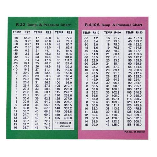
The pressure-temperature relationship in refrigerants is described by the vapor compression cycle, which is the fundamental principle behind most refrigeration and air conditioning systems. The relationship is defined by the refrigerant's properties and its phase changes between the liquid and vapor states. Here are the key points regarding the pressure-temperature relationship:

  1. Saturation Pressure-Temperature Relationship: When a refrigerant is in a saturated state, its pressure and temperature are related. This relationship is defined by the refrigerant's pressure-temperature chart or table. For a given refrigerant, as its pressure increases, the corresponding saturation temperature also increases, and vice versa. This relationship is essential for determining the operating conditions of a refrigeration system.

  2. Evaporation: During the evaporation process, the refrigerant absorbs heat from the surroundings (e.g., air or water) and changes from a liquid to a vapor state. The refrigerant evaporates at a low temperature and low pressure in the evaporator, thereby extracting heat from the cooling medium.

  3. Compression: The compressor in a refrigeration system increases the pressure and temperature of the refrigerant vapor. As the refrigerant vapor is compressed, its temperature rises significantly.

  4. Condensation: The high-pressure, high-temperature refrigerant vapor then enters the condenser, where it releases heat to the surroundings and changes from a vapor to a liquid state. This process occurs at a high temperature and high pressure. The refrigerant's temperature gradually decreases as heat is dissipated to the cooling medium.

  5. Expansion: The high-pressure liquid refrigerant then passes through an expansion valve or an expansion device, which reduces its pressure and temperature. As a result, the refrigerant's temperature drops further, preparing it for the evaporation process to repeat.

It's important to note that the pressure-temperature relationship can vary between different refrigerants. Each refrigerant has its own unique pressure-temperature characteristics, which must be considered during system design, operation, and troubleshooting. Manufacturers provide specific pressure-temperature charts or tables for different refrigerants to guide engineers and technicians in understanding and working with the particular refrigerant being used.

Central Air Conditioning Plant Temperatures 

The temperatures of various air and water streams in a central air conditioning plant can vary depending on the specific design, system configuration, and operating conditions. However, here are some typical temperature ranges you might find in a central air conditioning plant:

  1. Supply Air Temperature: The supply air temperature refers to the temperature of the conditioned air leaving the air handling unit (AHU) or central cooling plant. It is typically set based on the cooling requirements of the building or specific zones and can range between 12-18°C (54-64°F) for cooling applications.

  2. Return Air Temperature: The return air temperature is the temperature of the air being drawn back into the central air conditioning plant from the conditioned spaces. It is often slightly higher than the supply air temperature due to the heat added by occupants, equipment, and other sources in the building. Return air temperatures can vary depending on the specific conditions but typically range between 20-25°C (68-77°F).

  3. Room Air Temperature: The room air temperature refers to the temperature of the air within the conditioned spaces, such as offices, classrooms, or retail areas. It is the temperature that occupants experience and is usually maintained within a comfortable range of 20-24°C (68-75°F).

  4. Chilled Water Inlet/Outlet Temperatures: In a water-cooled central air conditioning plant, chilled water is circulated through the chiller and cooling coils. The chilled water inlet temperature, which is the temperature of the water entering the chiller, typically ranges between 6-10°C (43-50°F). The chilled water outlet temperature, which is the temperature of the water leaving the chiller, can vary depending on the cooling load but is typically maintained between 12-16°C (54-61°F).

  5. Condenser Water Inlet/Outlet Temperatures: The condenser water is used to remove heat from the refrigerant in the condenser of a water-cooled chiller. The condenser water inlet temperature, which is the temperature of the water entering the condenser, is usually set higher than the ambient temperature. It can range between 26-32°C (79-90°F). The condenser water outlet temperature, which is the temperature of the water leaving the condenser, will depend on the heat load and cooling requirements but is typically higher than the inlet temperature.

It's important to note that these temperature ranges are general guidelines and can vary based on factors such as the specific cooling requirements, climate conditions, and system design considerations. The actual temperatures in a central air conditioning plant should be determined based on the particular project specifications, equipment selection, and operating conditions.

Monitoring the performance of an HVAC chiller plant 

Monitoring the performance of an HVAC chiller plant is crucial for ensuring its optimal operation and energy efficiency. Here are some steps to help you monitor the performance of an HVAC chiller plant:

  1. Collect Data: Install sensors and data loggers at various points in the chiller plant to measure relevant parameters such as temperatures, pressures, flow rates, power consumption, and operating hours. These sensors can be connected to a Building Management System (BMS) or a dedicated monitoring system.

  2. Establish Baseline: Determine the baseline performance of the chiller plant by collecting data over a representative period of normal operation. This baseline will serve as a reference for future comparisons.

  3. Define Key Performance Indicators (KPIs): Identify key metrics that indicate the performance of the chiller plant. Common KPIs for chiller plants include energy efficiency ratio (EER), coefficient of performance (COP), kilowatt per ton (kW/ton), and chiller plant capacity utilization.

  4. Real-Time Monitoring: Continuously monitor the performance of the chiller plant in real-time using the collected data. Use the BMS or dedicated monitoring system to analyze the data and display it in a user-friendly format. This will allow you to identify any deviations or anomalies promptly.

  5. Trend Analysis: Analyze the historical data to identify long-term trends in the chiller plant performance. Look for patterns or changes in KPIs over time that may indicate performance degradation or optimization opportunities.

  6. Alarm Systems: Set up an alarm system that alerts you when specific parameters go beyond predetermined thresholds. This will help you respond quickly to any abnormal conditions, such as high energy consumption or equipment malfunctions.

  7. Regular Auditing: Conduct periodic audits of the chiller plant performance to assess its efficiency and identify areas for improvement. This can include energy audits or commissioning activities to ensure the system is operating as intended.

  8. Benchmarking: Compare the performance of your chiller plant with industry standards or similar systems to gauge its efficiency and identify potential areas for optimization.

  9. Maintenance and Optimization: Regularly maintain and optimize the chiller plant based on the data and insights gathered. Perform routine maintenance tasks such as cleaning condenser coils, checking refrigerant levels, and inspecting insulation to ensure efficient operation.

  10. Continuous Improvement: Use the performance monitoring data to implement energy-saving strategies and operational improvements. This can involve adjusting setpoints, optimizing equipment schedules, or implementing advanced control strategies.

Remember, the specifics of monitoring may vary depending on the complexity and size of the chiller plant. It is recommended to consult with HVAC professionals or energy management experts to develop a comprehensive monitoring plan tailored to your specific chiller plant.

Improve the performance of an HVAC chiller

To improve the performance of an HVAC chiller, you can consider the following steps:

  1. Regular Maintenance: Ensure that the chiller undergoes routine maintenance as per the manufacturer's recommendations. This includes tasks such as cleaning condenser and evaporator coils, inspecting and tightening electrical connections, checking refrigerant levels, and lubricating moving parts. Regular maintenance helps maintain efficiency and prevents potential issues.

  2. Optimize Water Flow: Proper water flow through the chiller is essential for optimal performance. Ensure that the water flow rates are within the manufacturer's specifications. Check for any blockages, scale buildup, or clogged filters that could impede flow and reduce efficiency. Consider using variable speed drives or control valves to adjust flow rates based on load requirements.

  3. Optimal Refrigerant Charge: Ensure that the chiller has the correct refrigerant charge as specified by the manufacturer. An incorrect refrigerant charge can significantly impact performance and efficiency. Regularly check and adjust the refrigerant charge if necessary.

  4. Condenser and Evaporator Cleaning: Clean the condenser and evaporator coils regularly to remove dirt, debris, and scale buildup. Dirty coils reduce heat transfer efficiency and increase energy consumption. Use appropriate coil cleaning techniques and consider using coil coatings or treatments to minimize future dirt buildup.

  5. Improve Heat Transfer Efficiency: Enhance heat transfer efficiency by considering measures such as using water treatment to prevent scaling and fouling, installing efficient heat exchangers, or utilizing advanced heat transfer surfaces.

  6. Optimize Chilled Water Setpoints: Review the chilled water setpoints to ensure they are within the recommended range. Lowering the chilled water supply temperature can improve the cooling efficiency, but it may increase the chiller's energy consumption. Evaluate the trade-offs and optimize the setpoints based on the specific cooling requirements of the facility.

  7. Variable Speed Drives: Consider installing variable speed drives (VSDs) for the chiller and cooling tower fans. VSDs allow the fans to operate at varying speeds based on the cooling demand, resulting in energy savings and improved efficiency.

  8. Control Strategies: Implement advanced control strategies such as optimizing sequencing and staging of multiple chillers, utilizing predictive or adaptive control algorithms, and integrating the chiller plant with a Building Management System (BMS). These strategies can help optimize the chiller plant's operation and improve overall performance.

  9. Energy Efficiency Upgrades: Explore energy-efficient upgrades for the chiller plant, such as upgrading to more efficient chillers, pumps, or cooling towers. Evaluate the potential energy savings and payback period of these upgrades to determine their feasibility.

  10. Monitoring and Benchmarking: Continuously monitor the chiller plant's performance and compare it with industry benchmarks or similar systems. Use the monitoring data to identify areas for improvement and implement corrective actions accordingly.

Remember, it's essential to consult with HVAC professionals or chiller manufacturers for specific recommendations and guidance tailored to your chiller system. They can provide detailed insights based on the specific equipment, load requirements, and operating conditions of your HVAC system.

IKW

Input Kilowatts per Ton (IKW) is a metric used to assess the energy efficiency of an HVAC chiller plant. It represents the amount of electrical power input (in kilowatts) required to produce one ton of cooling capacity. IKW is calculated by dividing the total electrical power input to the chiller plant (in kilowatts) by the total cooling capacity of the chiller plant (in tons).

The formula to calculate IKW is as follows:

IKW = Total Power Input (kW) / Total Cooling Capacity (Tons)

The lower the IKW value, the more energy-efficient the chiller plant is considered to be. Achieving a lower IKW indicates that the chiller plant can deliver a given cooling capacity with less energy consumption.

IKW is often used as a performance indicator for comparing the energy efficiency of different chiller plants or for evaluating the efficiency improvements achieved through retrofits or upgrades. It allows facility managers and engineers to assess the chiller plant's energy performance and identify opportunities for optimization and energy savings.


Integrated Part Load Value (IPLV)

Calculating the Integrated Part Load Value (IPLV) for a chiller plant involves several steps. Here's a general procedure to calculate IPLV:

  1. Determine the Chiller Performance Data: Gather the performance data for the chiller(s) in the plant. This includes the chiller's cooling capacity, power input, and efficiency at various part-load conditions. The data is typically provided by the chiller manufacturer or can be obtained through performance testing.

  2. Determine the Weighting Factors: IPLV incorporates weighting factors for each part-load condition to represent their expected frequency of occurrence in a typical operating year. These factors are usually provided by industry standards or energy efficiency regulations specific to your region. Common weighting factors are 100% (full load), 75%, 50%, and 25% of the design load.

  3. Calculate Part Load Performance: For each part-load condition, multiply the chiller's cooling capacity by its efficiency at that load condition to obtain the cooling capacity in kilowatts (kW) delivered per ton of cooling capacity.

  4. Calculate Part Load Power: For each part-load condition, determine the chiller's power input in kilowatts (kW) at that load condition.

  5. Apply Weighting Factors: Multiply each part-load performance and power values calculated in steps 3 and 4 by their respective weighting factors.

  6. Sum the Weighted Values: Add up the weighted part-load performance values and the weighted part-load power values calculated in step 5.

  7. Calculate IPLV: Divide the sum of the weighted part-load power values by the sum of the weighted part-load performance values. The result is the IPLV, expressed as kW/ton.

The IPLV calculation provides a weighted average of the chiller plant's performance across various part-load conditions. It provides a more accurate representation of the chiller plant's energy efficiency under typical operating conditions.

Note that the specific formulas and requirements for IPLV calculations may vary depending on regional standards or energy efficiency regulations. It's recommended to refer to applicable standards or consult with industry professionals to ensure compliance and accuracy in the IPLV calculation for your specific chiller plant.

Evolution of VRV Technology


Variable Refrigerant Flow (VRF) technology has evolved significantly over the years, improving energy efficiency, flexibility, and overall performance. VRF systems are a type of HVAC (Heating, Ventilation, and Air Conditioning) technology that allows for varying the refrigerant flow to different indoor units in a building, providing more precise control over temperature in different zones. Here is an overview of the evolution of VRF technology:

  1. Introduction (1980s-1990s): VRF technology was first introduced in the 1980s, primarily by Japanese manufacturers. These early systems provided a more efficient alternative to traditional HVAC systems by enabling variable control of the refrigerant flow and zoning capabilities.

  2. Expansion and Global Adoption (2000s): In the 2000s, VRF technology gained popularity globally. Manufacturers continued to refine and expand their product offerings. The technology's ability to provide simultaneous heating and cooling in different zones and its energy efficiency contributed to its widespread adoption in commercial and residential buildings.

  3. Advancements in Inverter Technology (2000s-2010s): VRF systems incorporate inverter-driven compressors, allowing for variable speed operation. This technology improves energy efficiency by adjusting the compressor speed to match the current heating or cooling demand, resulting in reduced energy consumption and better comfort control.

  4. Enhanced System Design and Integration (2010s): Manufacturers focused on improving the overall design and integration of VRF systems. This included advancements in communication protocols, controls, and sensors, making it easier to integrate VRF systems with building automation systems (BAS) for centralized control and monitoring.

  5. Higher Efficiency and Eco-Friendly Refrigerants (2010s-2020s): As environmental concerns grew, manufacturers began developing VRF systems that used more environmentally friendly refrigerants with lower global warming potential (GWP). This shift was driven by regulatory changes and a broader industry commitment to sustainability.

  6. Smart Controls and Building Automation (2010s-2020s): VRF systems have become increasingly connected and equipped with smart controls. Building owners and operators can remotely monitor and control the HVAC system through web-based interfaces or mobile apps, optimizing energy usage and responding to changing occupancy patterns in real-time.

  7. Integration with Renewable Energy Sources (2020s): With a growing emphasis on renewable energy, VRF systems are being designed to integrate seamlessly with sources such as solar panels and geothermal systems. This integration enhances the overall sustainability of HVAC systems.

  8. Focus on Health and Indoor Air Quality (2020s): Recent developments in the VRF technology include features that contribute to better indoor air quality, such as advanced filtration options, humidity control, and ventilation capabilities. These features are particularly relevant in the context of increasing awareness of health and wellness in building design.

The evolution of VRF technology continues, driven by advancements in materials, controls, energy efficiency, and a commitment to environmental sustainability. As the industry progresses, we can expect further innovations that enhance the performance, efficiency, and user-friendliness of VRF systems.


Principles of working of variable refrigerant flow 


The Variable Refrigerant Flow (VRF) system is an advanced HVAC technology designed for more precise control over the heating and cooling of different zones within a building. The basic principles of the working of a VRF system involve the following key components and processes:

  1. Outdoor Unit:

    • The outdoor unit contains a compressor, condenser coil, and expansion valve.
    • The compressor pressurizes the refrigerant gas, raising its temperature.
    • The high-pressure, high-temperature refrigerant gas is then sent to the condenser coil to release heat to the external environment. This process transforms the refrigerant into a high-pressure liquid.
  2. Refrigerant Circulation:

    • The high-pressure liquid refrigerant is then circulated through a network of piping to the indoor units.
  3. Indoor Units (Fan Coil Units):

    • Each indoor unit, also known as a fan coil unit, is installed in a specific zone or room within the building.
    • The indoor unit consists of a heat exchanger, fan, and expansion valve.
    • The expansion valve controls the flow of refrigerant into the indoor unit. As the refrigerant expands, it absorbs heat from the indoor air.
  4. Variable Refrigerant Flow Control:

    • VRF systems are designed with variable refrigerant flow control mechanisms, typically utilizing inverter-driven compressors.
    • The inverter technology adjusts the speed of the compressor to match the specific heating or cooling requirements of the connected indoor units. This allows for precise temperature control and energy efficiency.
  5. Simultaneous Heating and Cooling:

    • A key feature of VRF systems is their ability to provide simultaneous heating and cooling to different zones within the building.
    • While one indoor unit may be in cooling mode, another can be in heating mode, contributing to enhanced comfort and flexibility.
  6. Zoning and Individual Control:

    • VRF systems are designed to create multiple zones within a building, each with its own individual temperature control.
    • Building occupants can set different temperature preferences for each zone, allowing for personalized comfort and energy savings.
  7. Communication and Controls:

    • VRF systems are equipped with advanced control systems that enable centralized monitoring and control of the entire HVAC system.
    • Smart controls and communication protocols allow for seamless integration with building automation systems (BAS) and enable remote monitoring and adjustments.
  8. Energy Efficiency:

    • The variable refrigerant flow control and inverter-driven compressors contribute to energy efficiency by adjusting the system's capacity to match the actual demand. This reduces energy consumption during periods of lower heating or cooling requirements.
  9. Quiet Operation:

    • VRF systems often operate more quietly than traditional HVAC systems, providing a more comfortable and less intrusive indoor environment.

In summary, the working principles of a Variable Refrigerant Flow (VRF) system involve the precise control of refrigerant flow to individual indoor units, simultaneous heating and cooling capabilities, zoning for personalized comfort, and advanced controls for energy efficiency and system optimization. These features make VRF systems suitable for a wide range of applications, including commercial and residential buildings.


Working of a digital compressor used in variable refrigerant flow machine (BRAC) 

In a Variable Refrigerant Flow (VRF) system, the digital compressor plays a crucial role in controlling the flow of refrigerant and maintaining the desired temperature within the system. The term "digital compressor" often refers to a compressor that uses digital technology, such as an inverter-driven compressor. Here's an overview of how a digital compressor works in a VRF system:

  1. Inverter Technology:

    • The digital compressor in a VRF system typically employs inverter technology. Unlike traditional compressors that operate at a fixed speed, inverter-driven compressors can vary their speed to match the current heating or cooling requirements of the connected indoor units.
  2. Variable Speed Operation:

    • The inverter within the digital compressor converts the incoming electrical power into variable-frequency power.
    • By adjusting the frequency of the power supply, the inverter controls the speed of the compressor motor. This variable-speed operation allows the compressor to modulate its capacity based on the real-time demands of the indoor units.
  3. Precise Control of Refrigerant Flow:

    • The variable-speed operation of the digital compressor enables precise control of the refrigerant flow within the VRF system.
    • During periods of high demand, the compressor speeds up to provide more cooling or heating capacity. Conversely, during periods of lower demand, the compressor slows down to reduce capacity, contributing to energy efficiency and avoiding unnecessary cycling.
  4. Energy Efficiency:

    • One of the key advantages of digital compressors is their ability to operate at partial load conditions efficiently.
    • Traditional compressors are either on or off, leading to energy-intensive start-stop cycles. In contrast, the digital compressor's ability to modulate its speed allows it to match the actual load, reducing energy consumption and improving overall system efficiency.
  5. Soft Start and Smooth Operation:

    • Digital compressors have a soft start feature, meaning they start gradually rather than abruptly reaching full speed. This reduces the stress on the compressor and other system components, extending the overall lifespan of the equipment.
    • The smooth, continuous operation of the compressor contributes to quieter performance, making VRF systems suitable for environments where low noise levels are essential.
  6. Temperature Control and Zoning:

    • The variable refrigerant flow control provided by the digital compressor facilitates precise temperature control in different zones or rooms within the building.
    • As the demand for heating or cooling changes in specific zones, the digital compressor adjusts its speed accordingly, allowing for simultaneous heating and cooling in different areas.

In summary, the working of a digital compressor in a Variable Refrigerant Flow (VRF) system involves inverter technology, variable-speed operation, and precise control of refrigerant flow. This technology enhances energy efficiency, enables precise temperature control, and contributes to the overall performance and comfort provided by VRF systems.


Working of inverter compressor used in variable refrigerant flow machine  (BRAC)

The inverter compressor is a critical component in Variable Refrigerant Flow (VRF) systems, contributing to their energy efficiency and precise temperature control. Here's an overview of how an inverter compressor works in a VRF system:

  1. Variable Speed Operation:

    • The inverter compressor is designed to operate at variable speeds. Unlike traditional compressors that operate at a fixed speed and turn on or off based on demand, inverter compressors can adjust their speed continuously to match the actual heating or cooling requirements of the system.
  2. Inverter Technology:

    • The inverter, a device that converts AC (alternating current) to DC (direct current) and vice versa, is a key part of the inverter compressor.
    • When the demand for heating or cooling is low, the inverter adjusts the speed of the compressor to a lower level, reducing energy consumption. Conversely, when the demand is high, the inverter increases the compressor speed to provide more capacity.
  3. Soft Start:

    • One of the benefits of inverter compressors is their ability to start softly. Instead of starting at full speed immediately, the inverter allows the compressor to gradually reach the required speed. This reduces the stress on the compressor and other system components, leading to smoother operation and extending the lifespan of the equipment.
  4. Precise Temperature Control:

    • The variable speed operation of the inverter compressor allows for precise temperature control in different zones or rooms within a building.
    • As the demand for heating or cooling changes in specific areas, the compressor adjusts its speed accordingly. This enables the VRF system to maintain a consistent and comfortable indoor temperature.
  5. Energy Efficiency:

    • Inverter compressors contribute significantly to the energy efficiency of VRF systems. By adjusting their speed based on the actual demand, these compressors avoid the energy-intensive start-stop cycles associated with traditional compressors.
    • The ability to operate efficiently at partial loads enhances overall system efficiency and reduces energy consumption, leading to cost savings over time.
  6. Simultaneous Heating and Cooling:

    • Inverter compressors enable VRF systems to provide simultaneous heating and cooling in different zones. This is achieved by modulating the refrigerant flow to individual indoor units based on the specific heating or cooling requirements of each zone.
  7. Quiet Operation:

    • The gradual start and variable speed operation of inverter compressors contribute to quieter system performance. This is particularly important in environments where low noise levels are essential.

In summary, the inverter compressor in a Variable Refrigerant Flow (VRF) system works by adjusting its speed based on the heating or cooling demands of the connected indoor units. This variable-speed operation enhances energy efficiency, allows for precise temperature control, and contributes to the overall performance and comfort of the VRF system. 


Comparison of variable refrigerant flow machine versus a standard split air conditioner (BRAC)

The comparison between a Variable Refrigerant Flow (VRF) system and a standard split air conditioner involves several key factors, including energy efficiency, flexibility, simultaneous heating and cooling, zoning capabilities, and system complexity. Here's a breakdown of the differences between the two:

  1. Energy Efficiency:

    • VRF System: VRF systems are known for their high energy efficiency. The use of inverter-driven compressors allows the system to adjust its capacity based on the actual heating or cooling demands, avoiding the on/off cycling associated with traditional split systems. This results in better energy efficiency and reduced operating costs.
    • Standard Split AC: Traditional split air conditioners operate at a fixed speed and have limited capacity control. They tend to cycle on and off to maintain the set temperature, which can be less energy-efficient compared to VRF systems, especially during partial load conditions.
  2. Flexibility and Zoning:

    • VRF System: VRF systems offer superior flexibility and zoning capabilities. They can provide simultaneous heating and cooling to different zones within a building, allowing for personalized temperature control in individual rooms. The variable refrigerant flow control enables precise adjustment of the refrigerant flow to each indoor unit.
    • Standard Split AC: Split air conditioners are typically designed for single-zone applications, where one indoor unit is connected to one outdoor unit. Zoning capabilities are limited, and separate systems are needed for different zones, making them less flexible compared to VRF systems.
  3. Simultaneous Heating and Cooling:

    • VRF System: VRF systems excel in providing simultaneous heating and cooling to different zones. This is achieved by modulating the refrigerant flow to individual indoor units based on their specific heating or cooling requirements.
    • Standard Split AC: Traditional split systems are designed for either cooling or heating, and they cannot provide both functions simultaneously to different areas.
  4. Installation and System Complexity:

    • VRF System: Installing a VRF system can be more complex than a standard split AC, mainly due to the need for additional refrigerant piping and the integration of multiple indoor units with a single outdoor unit. However, the complexity can offer greater design flexibility for larger, multi-zone applications.
    • Standard Split AC: Standard split systems are relatively simpler to install and are commonly used for smaller residential or single-room applications.
  5. Cost:

    • VRF System: VRF systems generally have a higher upfront cost compared to standard split AC units, mainly due to their advanced technology and flexibility. However, the long-term energy savings may offset the initial investment.
    • Standard Split AC: Standard split AC units are typically more cost-effective for smaller applications and can be a suitable choice for budget-conscious consumers.

In summary, Variable Refrigerant Flow (VRF) systems and standard split air conditioners serve different needs. VRF systems are ideal for larger, multi-zone applications where flexibility, energy efficiency, and simultaneous heating and cooling are essential. Standard split AC units are more straightforward and cost-effective, making them suitable for smaller residential or single-room applications with less complex requirements.


Introduction the psychometric chart 


The psychrometric chart is a graphical representation of the thermodynamic properties of air. It is a valuable tool used in the field of HVAC (Heating, Ventilation, and Air Conditioning) engineering to analyze and understand the air conditioning processes, assess comfort conditions, and design or troubleshoot air conditioning systems. The chart provides a visual representation of the relationships between various air properties under different conditions.

Key components and concepts on a psychrometric chart include:

  1. Axes:

    • The chart typically has two main axes - the horizontal axis represents dry-bulb temperature (DBT), which is the actual air temperature, and the vertical axis represents humidity ratio or specific humidity.
  2. Lines of Constant Properties:

    • Lines of constant dry-bulb temperature (isotherms) run horizontally across the chart.
    • Lines of constant humidity ratio (isohumes) slope diagonally.
    • Lines of constant enthalpy (total heat content) are often included, and they slope upward to the right.
  3. Specific Humidity:


Comfort Zone in psychrometrics 


The comfort zone in psychrometrics refers to the range of conditions on a psychrometric chart where occupants typically feel comfortable in terms of temperature and humidity. Psychrometrics is the study of the thermodynamic properties of air and their relationships, often represented graphically on a psychrometric chart. The comfort zone is crucial for HVAC (Heating, Ventilation, and Air Conditioning) professionals as it helps guide the design of systems that maintain optimal conditions for human comfort.

Key features of the comfort zone in psychrometrics include:

  1. Temperature Range:

    • The comfort zone is generally associated with a range of dry-bulb temperatures, which is the actual air temperature measured with a standard thermometer.
    • The typical comfort range for dry-bulb temperature is between 20°C (68°F) and 27°C (80.6°F). This range provides conditions where people are likely to feel comfortable.
  2. Relative Humidity Range:

    • In addition to temperature, relative humidity (RH) plays a crucial role in comfort. Relative humidity is the ratio of the actual amount of moisture in the air to the maximum amount it could hold at that temperature.
    • The comfort zone typically maintains a relative humidity range between 30% and 60%. This range helps prevent the air from being too dry or too humid, contributing to a comfortable indoor environment.
  3. ASHRAE Standards:

    • ASHRAE (American Society of Heating, Refrigerating and Air-Conditioning Engineers) provides guidelines and standards for indoor environmental conditions, including the comfort zone.
    • ASHRAE Standard 55, for example, specifies conditions for thermal comfort and recommends temperature and humidity ranges within which the majority of occupants are likely to feel comfortable.
  4. Comfort Indices:

    • Comfort indices, such as the Predicted Mean Vote (PMV) and Predicted Percentage Dissatisfied (PPD), are used to quantify the comfort level based on factors like temperature, humidity, air speed, and clothing insulation.
    • These indices help HVAC professionals assess and design systems that provide an environment that meets or exceeds comfort expectations.
  5. Comfort Envelope:

    • The comfort zone is often depicted as an envelope on the psychrometric chart, encompassing combinations of temperature and humidity where people generally feel comfortable.
    • The shape and size of this envelope may vary based on specific standards, local climate considerations, and the preferences of the occupants.

It's important to note that individual comfort preferences can vary, and other factors such as clothing, activity level, and personal acclimatization also influence perceived comfort. The psychrometric chart and associated comfort considerations guide HVAC professionals in designing systems that cre


Dry bulb temperature in psychometrics

Dry bulb temperature is a fundamental and straightforward measurement used in psychrometrics, the branch of thermodynamics that deals with the properties of air and their relationships. Dry bulb temperature is a primary indicator of the thermal condition of the air and is one of the parameters plotted on a psychrometric chart.

Here are key points about dry bulb temperature in psychrometrics:

  1. Definition:

    • Dry bulb temperature (DBT) is the air temperature measured with a standard thermometer. It represents the actual temperature of the air, and it is the most commonly reported temperature in weather forecasts.
    • The term "dry bulb" is used to distinguish this measurement from other temperature-related parameters in psychrometrics.
  2. Measurement:

    • Dry bulb temperature is measured using a standard thermometer placed in the air without any moisture-related influence. It provides the temperature reading without considering the effects of humidity or moisture content in the air.
  3. Units:

Wet bulb temperature psychrometrics (BARC)

Wet bulb temperature is another important parameter in psychrometrics, providing information about the cooling effect of moisture in the air. It is one of the key measurements represented on a psychrometric chart. Here are key points about wet bulb temperature in psychrometrics:

  1. Definition:

    • Wet bulb temperature (WBT) is the temperature recorded by a thermometer with its bulb covered in a wet wick. As the moisture evaporates from the wick, it causes a cooling effect on the thermometer bulb, and the wet bulb temperature is lower than the dry bulb temperature.
  2. Measurement:

    • Wet bulb temperature is measured using a psychrometer, which consists of two thermometers—one with a dry bulb and another with a wet bulb. The difference in temperature between the dry and wet bulbs is used to calculate the wet bulb temperature.
  3. Units:

    • Wet bulb temperature is typically expressed in degrees Celsius (°C) or Fahrenheit (°F). On a psychrometric chart, it is represented along the vertical axis.
  4. Representation on Psychrometric Chart:

    • Lines of constant wet bulb temperature, known as adiabatic saturation lines, slope diagonally across the psychrometric chart. These lines represent the conditions at which air is saturated with moisture (100% relative humidity).
  5. Cooling Effect of Evaporation:

    • Wet bulb temperature is an indicator of the cooling effect of evaporation. As moisture evaporates from the wet bulb, it absorbs heat from the surrounding air, causing the wet bulb temperature to drop.
  6. Dew Point Relationship:

    • The wet bulb temperature is related to the dew point temperature. When air is saturated (100% relative humidity), the wet bulb and dew point temperatures are equal.
  7. Comfort Assessment:

    • Wet bulb temperature, in conjunction with dry bulb temperature, is used to assess thermal comfort. Psychrometric charts and comfort indices consider both temperatures to determine the range of conditions where people are likely to feel comfortable.
  8. Adiabatic Saturation Process:

    • The process of moving along a constant wet bulb temperature line on the psychrometric chart represents an adiabatic saturation process. This process simulates the addition of moisture to the air without changing its enthalpy (total heat content).
  9. HVAC System Design:

    • Wet bulb temperature is a crucial parameter in the design and analysis of air conditioning systems. It helps determine the potential for evaporative cooling and influences the system's performance in different climates.

Understanding the wet bulb temperature is essential for HVAC professionals and meteorologists, as it provides insights into the cooling potential and moisture content of the air. Psychrometric charts, which include wet bulb temperature lines, are valuable tools in assessing and designing systems for various applications..


Saturation line psychrometrics (BARC)

The saturation line on a psychrometric chart is a significant feature that represents the conditions at which air is saturated with moisture, resulting in 100% relative humidity. This line is also known as the saturation curve or the saturation mixing ratio line. Here are key points about the saturation line in psychrometrics:

  1. Definition:

    • The saturation line represents the boundary between saturated air (100% relative humidity) and unsaturated air on a psychrometric chart. It denotes the maximum amount of moisture air can hold at a given temperature.
  2. Saturated Air:

    • Any point on the saturation line corresponds to air that is fully saturated with moisture. In other words, the air cannot hold any more water vapor at that specific temperature.
  3. Adiabatic Saturation:

    • The process of moving along the saturation line is an adiabatic saturation process. It simulates the addition of moisture to the air without changing its enthalpy (total heat content).
    • Adiabatic saturation is the process of adding moisture to unsaturated air without changing its dry bulb temperature. The air follows the saturation line until it becomes saturated.
  4. Dew Point and Wet Bulb Temperature:

    • The saturation line intersects with lines of constant dew point temperature and constant wet bulb temperature. The dew point temperature is the temperature at which air becomes saturated, and the wet bulb temperature is the lowest temperature air can reach through evaporation.
  5. Enthalpy:

    • The enthalpy along the saturation line remains constant. Enthalpy is the total heat content of the air and includes both sensible heat and latent heat associated with moisture.
  6. Sensible Heat and Latent Heat:

    • The horizontal distance from the saturation line to the left along a constant dry bulb temperature line represents sensible heat, while the vertical distance upwards represents latent heat (associated with the moisture content).
  7. Humidity Ratio:

    • The humidity ratio or specific humidity along the saturation line is the maximum amount of moisture air can hold at a given temperature. It is a key parameter in psychrometrics.
  8. Use in HVAC Design:

    • HVAC professionals use the saturation line and other psychrometric chart features to design air conditioning systems. Understanding the conditions along the saturation line helps in assessing humidity control, dew point considerations, and cooling processes.
  9. Psychrometric Processes:

    • Different psychrometric processes, such as heating, cooling, humidification, and dehumidification, involve movement along or away from the saturation line, depending on the specific conditions and requirements.

In summary, the saturation line on a psychrometric chart is a critical reference that indicates the conditions of saturated air at various temperatures. It plays a key role in understanding humidity, designing HVAC systems, and analyzing psychrometric processes related to air conditioning and comfort.


Dew point temperature psychrometric (BARC)

Dew point temperature is a key parameter in psychrometrics, representing the temperature at which air becomes saturated with moisture and starts to undergo condensation. It is an important metric for assessing humidity conditions and is often depicted on a psychrometric chart. Here are key points about dew point temperature in psychrometrics:

  1. Definition:

    • Dew point temperature is the temperature at which air becomes saturated with moisture, leading to the formation of dew or condensation. It is the temperature at which the air reaches 100% relative humidity.
  2. Measurement:

    • Dew point temperature is determined by cooling a sample of air at constant pressure until saturation is reached. The temperature at which saturation occurs is the dew point temperature.
    • On a psychrometric chart, the dew point temperature is typically represented by lines of constant dew point.
  3. Relation to Saturation Line:

    • The dew point temperature is directly related to the saturation line on the psychrometric chart. When air is cooled at constant pressure, it follows the saturation line until saturation is achieved, and the dew point temperature is reached.
  4. Indication of Humidity:

    • The dew point temperature is a useful indicator of humidity. A higher dew point temperature indicates higher moisture content in the air, while a lower dew point temperature suggests drier air.
  5. Comfort and Perception of Humidity:

    • Dew point temperature plays a role in how people perceive humidity. Higher dew points can lead to a feeling of stickiness and discomfort, especially in warmer conditions. Lower dew points are associated with drier and more comfortable air.
  6. Condensation and Dew Formation:

    • When the air temperature drops to the dew point temperature, the air becomes saturated, and excess moisture condenses into visible water droplets, forming dew on surfaces.
    • Dew point temperature is crucial in understanding the potential for dew formation on surfaces, including building materials and equipment.
  7. Psychrometric Chart Representation:

    • On a psychrometric chart, lines of constant dew point temperature run parallel to the saturation line. The closer these lines are, the higher the humidity.
  8. HVAC Design and Control:

    • In HVAC systems, knowledge of the dew point temperature is essential for preventing issues like condensation on surfaces and controlling indoor humidity levels.
    • HVAC designers use dew point considerations to set appropriate temperature and humidity control strategies.
  9. Relationship with Wet Bulb Temperature:

    • The dew point temperature is closely related to the wet bulb temperature. The two temperatures are equal when the air is saturated.

In summary, dew point temperature is a critical parameter in psychrometrics, providing insights into humidity conditions, potential for condensation, and comfort perception. Understanding dew point temperature is valuable in various applications, including HVAC design, weather analysis, and the assessment of moisture-related issues.


Relative humidity psychrometrics (BARC)

Relative humidity (RH) is a key parameter in psychrometrics, representing the ratio of the actual amount of moisture in the air to the maximum amount it could hold at a given temperature. Relative humidity is crucial for understanding the moisture content of air and is commonly used in weather analysis and HVAC (Heating, Ventilation, and Air Conditioning) design. Here are key points about relative humidity in psychrometrics:

  1. Definition:

    • Relative humidity is expressed as a percentage and represents the ratio of the actual water vapor pressure in the air to the saturation water vapor pressure at the same temperature.
  2. Calculation:

    • The formula for calculating relative humidity is: Relative Humidity (RH)=(Actual Water Vapor PressureSaturation Water Vapor Pressure)×100
    • Relative humidity can also be approximated using the dew point temperature and dry bulb temperature.
  3. Psychrometric Chart Representation:

    • On a psychrometric chart, lines of constant relative humidity run parallel to the saturation curve (100% relative humidity line). These lines are often referred to as isohyets or lines of constant humidity ratio.
  4. Comfort Considerations:

    • Relative humidity is a crucial factor in assessing human comfort. The perception of comfort is influenced by both temperature and humidity. For example, high humidity levels can make a given temperature feel warmer and may lead to discomfort.
  5. Condensation and Dew Point:

    • When the air is cooled, its capacity to hold moisture decreases. If the air cools to the point where it reaches 100% relative humidity, further cooling will lead to condensation. The temperature at which condensation occurs is known as the dew point.
  6. Seasonal and Geographic Variation:

    • Relative humidity levels can vary significantly based on geographical location, time of day, and seasonal changes. Coastal areas may experience higher relative humidity, while deserts may have lower relative humidity levels.
  7. HVAC System Design:

    • In HVAC design, understanding and controlling relative humidity is essential for maintaining indoor air quality, preventing mold growth, and ensuring occupant comfort.
    • ASHRAE (American Society of Heating, Refrigerating and Air-Conditioning Engineers) standards provide guidelines for indoor relative humidity levels in different environments.
  8. Weather Analysis:

    • Meteorologists use relative humidity as a key parameter in weather analysis. It influences the likelihood of precipitation, cloud formation, and other atmospheric phenomena.
  9. Drying and Evaporation:

    • Relative humidity is a critical factor in processes involving drying or evaporation. When the air is already saturated (100% relative humidity), further drying or evaporation becomes more challenging.

Understanding and controlling relative humidity is essential in various applications, from maintaining indoor comfort to preserving materials and optimizing industrial processes. Psychrometric charts provide a visual representation of the relationships between temperature, humidity, and other air properties.


Absolute humidity psychrometric (BARC)

Absolute humidity is a measure of the actual amount of water vapor present in the air, typically expressed in terms of mass or volume. Unlike relative humidity, which is expressed as a percentage and depends on the air temperature, absolute humidity provides a more direct measure of the moisture content in the air. Here are key points about absolute humidity in psychrometrics:

  1. Definition:

    • Absolute humidity refers to the total mass or volume of water vapor per unit of air. It is an absolute measure of the moisture content and is not influenced by changes in air temperature.
  2. Units:

    • The units for expressing absolute humidity can vary. Common units include:
      • Mass-Based Units: Kilograms of water vapor per unit volume of air (e.g., kg/m³).
      • Volume-Based Units: Cubic meters of water vapor per unit volume of air (e.g., m³/m³).
  3. Calculation:

    • The calculation of absolute humidity involves measuring the actual amount of water vapor present in a given volume of air. It is often determined through direct measurements using devices such as humidity sensors or psychrometers.
  4. Psychrometric Chart Representation:

    • Absolute humidity is not directly represented on a standard psychrometric chart. However, it can be related to other psychrometric parameters, such as specific humidity, which is the mass of water vapor per unit mass of dry air.
  5. Relation to Specific Humidity:

    • Specific humidity and absolute humidity are closely related. Specific humidity is the ratio of the mass of water vapor to the total mass of air (dry and moist components). The two are essentially equivalent when expressed in mass-based units.
  6. Use in HVAC Design:

    • Absolute humidity is a crucial parameter in HVAC design, especially in processes related to dehumidification. HVAC systems are designed to control absolute humidity levels to ensure indoor comfort and prevent issues such as mold growth and moisture-related damage.
  7. Moisture Load and Sensible Heat:

    • Understanding absolute humidity is important in assessing the moisture load in the air. It also influences the sensible heat, which is the heat associated with changes in dry bulb temperature.
  8. Drying and Evaporation Processes:

    • Absolute humidity is considered in applications involving drying or evaporation. It helps determine the amount of moisture that can be absorbed or released during these processes.
  9. Weather and Climate Analysis:

    • Absolute humidity is a key parameter in meteorology for analyzing weather patterns and understanding the moisture content of the atmosphere.

While relative humidity is often used to describe the humidity level in weather reports, absolute humidity provides a more direct measure of the actual moisture content in the air. Both parameters are important in various fields, including HVAC, meteorology, and industrial processes.

Precipitation psychrometrics (BARC) 

Psychrometrics primarily deals with the thermodynamic properties of air and their relationships, focusing on parameters such as temperature, humidity, and air composition. Precipitation, on the other hand, is a meteorological phenomenon related to the condensation and subsequent falling of water or ice particles from the atmosphere to the Earth's surface.

While psychrometrics doesn't directly address precipitation, the study of air properties is crucial in understanding the processes leading to precipitation. Here's how the concepts intersect:

  1. Relative Humidity and Precipitation:

    • Relative humidity (RH), a key parameter in psychrometrics, plays a role in the formation of precipitation. When air becomes saturated (100% relative humidity), further cooling may lead to the condensation of water vapor into visible droplets or ice crystals, forming clouds. If the cloud particles grow large enough, precipitation in the form of rain, snow, sleet, or hail may occur.
  2. Dew Point and Precipitation:

    • The dew point temperature, another psychrometric parameter, is the temperature at which air becomes saturated, leading to the formation of dew or frost. In the context of precipitation, when the air cools to the dew point temperature and becomes saturated, it can contribute to the formation of cloud particles and potentially lead to precipitation.
  3. Moisture Content and Precipitation:

    • Absolute humidity or specific humidity, which measures the moisture content of air, is indirectly related to precipitation. High moisture content in the air contributes to the availability of water vapor for condensation and cloud formation, which are essential steps in the precipitation process.
  4. Psychrometrics in Weather Analysis:

    • Psychrometric charts are not typically used to directly analyze or predict precipitation. However, understanding air properties, temperature, and humidity is essential for meteorologists who use a range of tools and models to forecast weather conditions, including the likelihood of precipitation.
  5. Cloud Formation:

    • The process of cloud formation involves the cooling of air, which can be related to psychrometric principles. As air rises and cools, it may reach its dew point temperature, leading to the condensation of water vapor and the formation of clouds, which are precursors to precipitation.

In summary, while psychrometrics is not a direct tool for predicting or analyzing precipitation, the principles of air properties, relative humidity, and temperature play a role in understanding the atmospheric conditions that lead to cloud formation and ultimately influence precipitation. Meteorologists use a combination of meteorological instruments, models, and observational data to make predictions about weather, including the likelihood and type of precipitation.


Sources of heat in air conditioning 

 In air conditioning systems, the goal is to control the temperature and humidity of indoor air to create a comfortable and healthy environment. The process involves removing heat from the indoor space and expelling it outside. Several sources contribute to the heat that needs to be managed in air conditioning systems. Here are the primary sources of heat in air conditioning:

  1. Internal Heat Sources:

    • Occupants: The heat generated by the people inside a building contributes significantly to the overall heat load. The number of occupants, their activity levels, and metabolic rates impact the internal heat gain.
    • Appliances and Electronics: Electronic devices, lighting, and various appliances generate heat when in operation. The heat produced by computers, refrigerators, ovens, and other electrical equipment contributes to the overall thermal load.
  2. Solar Heat Gain:

    • Solar Radiation: Sunlight entering through windows or other openings can lead to solar heat gain. The radiant energy from the sun warms surfaces and increases the temperature inside the building. This effect is particularly pronounced in areas with large windows or glass facades.
  3. Ventilation Air:

    • Outdoor Air: When outdoor air is introduced for ventilation purposes, it may carry heat from the external environment into the indoor space. Depending on the outdoor temperature, this can add to the cooling load in warm climates or the heating load in cold climates.
  4. Infiltration and Exfiltration:

    • Air Leakage: Uncontrolled air leakage through openings in the building envelope, such as cracks or gaps, can allow outdoor air to enter or conditioned air to escape. This can introduce heat or remove cooled air, affecting the overall thermal balance.
  5. Building Envelope:

    • Conduction and Convection: Heat can be transferred into or out of a building through the walls, roof, and floor. The thermal conductivity of building materials determines how much heat is conducted through them. Additionally, convective heat transfer can occur through air movement around the building envelope.
  6. Humidity Control:

    • Latent Heat: The moisture content in the air, or humidity, contributes to the overall heat load. The process of removing moisture from the air involves removing latent heat. This is particularly relevant in climates with high humidity levels.
  7. Appliance and Equipment Heat:

    • HVAC System Components: The operation of the air conditioning system itself generates heat. The compressor, condenser, and other components produce thermal energy as they work to transfer heat from the indoor to the outdoor environment.

Effectively managing these sources of heat is essential for designing and operating energy-efficient air conditioning systems. Proper insulation, solar shading, ventilation strategies, and efficient HVAC equipment contribute to optimizing the overall performance of the system and maintaining comfort indoors.


Instantaneous heat load estimation format 

Estimating the instantaneous heat load in a building involves considering various factors such as occupancy, equipment usage, lighting, solar radiation, and more. The format for estimating the instantaneous heat load can be customized based on specific requirements and the complexity of the analysis. Here's a simplified format that you can use as a starting point:

Instantaneous Heat Load Estimation Format

Building Information:

  • Building Name/ID:
  • Location:
  • Type of Building:
  • Floor Area (m² or ft²):
  • Number of Floors:
  • Occupancy Type:

Internal Heat Sources:

  1. Occupancy:

    • Number of Occupants:
    • Occupancy Schedule:
    • Metabolic Rate per Occupant:
    • Sensible Heat Gain per Occupant:
  2. Appliances and Electronics:

    • List of Appliances/Equipment:
    • Power Rating (Wattage) for Each:
    • Usage Schedule:
    • Total Sensible Heat Gain from Appliances:
  3. Lighting:

    • Type of Lighting (Incandescent, LED, etc.):
    • Total Lighting Power (Watts):
    • Lighting Schedule:
    • Sensible Heat Gain from Lighting:

External Heat Sources:

  1. Solar Heat Gain:
    • Orientation of Windows/Facade:
    • Window Area:
    • Solar Heat Gain Coefficient (SHGC) for Windows:
    • Solar Radiation Intensity:
    • Sensible Heat Gain from Solar Radiation:

Ventilation and Infiltration:

  1. Ventilation Air:

    • Outdoor Airflow Rate:
    • Outdoor Air Temperature:
    • Enthalpy Difference (Indoor - Outdoor):
    • Sensible Heat Gain from Ventilation:
  2. Infiltration and Exfiltration:

    • Air Leakage Rate:
    • Enthalpy Difference (Indoor - Outdoor):
    • Sensible Heat Gain/Loss from Air Leakage:

Building Envelope:

  1. Conduction and Convection:
    • U-Values of Walls, Roof, Floor, Windows, etc.:
    • Temperature Difference (Indoor - Outdoor):
    • Sensible Heat Gain/Loss through Building Envelope:

Humidity Control:

  1. Latent Heat:
    • Moisture Generation Rate:
    • Specific Humidity Increase:
    • Latent Heat Gain:

HVAC System:

  1. HVAC System Heat Load:
    • Heat Gain/Loss from HVAC Components:
    • Cooling/Heating Capacity of the HVAC System:
    • Operating Schedule:
    • Total Sensible and Latent Heat Load:

Summary:

  1. Total Instantaneous Heat Load:
    • Sum of Sensible and Latent Heat Gains:

Notes:

  • Provide additional notes or comments regarding assumptions, design considerations, or any specific details impacting heat load.
  • Consider units consistently throughout the document (e.g., Watts, Kilowatts, Celsius, etc.).

This format provides a structured approach to estimating the instantaneous heat load in a building. Keep in mind that this is a basic template, and additional details or modifications may be necessary based on the specific characteristics of the building and the level of detail required for the analysis.

History of refrigeration


The history of refrigeration is a fascinating journey that spans centuries and involves numerous inventors and innovations. The development of refrigeration technology has had a profound impact on various industries, food preservation, and the overall comfort of human life. Here is a brief overview of the key milestones in the history of refrigeration:

  1. Early Concepts (Pre-18th Century):

    • Early civilizations, such as the ancient Egyptians and Chinese, used various methods to cool food, including storing it in cool, shaded areas or using ice and snow.
    • In the 17th century, natural ice harvesting became a common practice in colder regions.
  2. Evaporation and Cooling (18th Century):

    • In 1755, Scottish professor William Cullen demonstrated artificial refrigeration by evaporating ethyl ether in a vacuum, causing cooling.
    • In 1805, American inventor Oliver Evans designed the first refrigeration machine, but it was not practical for widespread use.
  3. Ice Harvesting and Distribution (19th Century):

    • The ice industry grew during the 19th century, with the development of ice harvesting, storage, and transportation techniques.
    • Frederick Tudor, known as the "Ice King," established a successful business harvesting and exporting ice from Massachusetts to the Caribbean.
  4. Compression Refrigeration (Mid-19th Century):

    • In 1834, Jacob Perkins and John Harrison patented a working vapor-compression refrigeration system using ether. However, it was financially unsuccessful.
    • In 1856, James Harrison, an Australian, built an ice-making machine using vapor-compression refrigeration, making him a pioneer in the field.
  5. Commercial Refrigeration (Late 19th Century):

    • The first practical and successful refrigeration machine for commercial use was developed by Carl von Linde in Germany in the 1870s. He used ammonia as the refrigerant.
    • In 1876, Carl Paul Gottfried Linde received a patent for an improved process for liquefying gases, which laid the foundation for modern refrigeration technology.
  6. Domestic Refrigeration (Early 20th Century):

    • General Electric introduced the first electric household refrigerator in 1911, called the "Monitor-Top." It used a sulfur dioxide and methyl formate refrigerant.
    • In 1927, the Frigidaire Corporation, a subsidiary of General Motors, introduced the first self-contained refrigeration unit.
  7. Chlorofluorocarbon (CFC) Refrigerants (Mid-20th Century):

    • In the 1930s, CFCs, such as Freon, were introduced as non-toxic and non-flammable refrigerants. They became widely used in various refrigeration and air conditioning applications.
  8. Modern Refrigeration (Late 20th Century to Present):

    • The late 20th century saw advancements in refrigeration technology, including the development of more environmentally friendly refrigerants due to concerns about ozone depletion and global warming.
    • Innovations in energy efficiency, digital controls, and smart technologies have continued to improve the performance of refrigeration systems.
  9. Regulations and Environmental Concerns:

    • The 1987 Montreal Protocol called for the phase-out of ozone-depleting substances, including many traditional refrigerants like CFCs. This led to the development and adoption of ozone-friendly refrigerants.
  10. Sustainability and Energy Efficiency (21st Century):

    • Recent years have seen a focus on sustainability and energy efficiency in refrigeration technologies, with efforts to reduce the environmental impact and improve overall system performance.

The history of refrigeration is marked by a series of inventions and innovations that have transformed the way we live, work, and store perishable goods. It has played a crucial role in the development of various industries, from food preservation to healthcare and beyond.

Domestic Refrigerators 


Domestic refrigerators are common household appliances designed for storing and preserving food, beverages, and other perishable items at low temperatures. These appliances use a combination of refrigeration principles, insulation, and temperature control to create a suitable environment for extending the shelf life of various products. Here are key features and components of domestic refrigerators:

  1. Compressor:

    • The heart of the refrigeration system is the compressor. It pressurizes the refrigerant gas, causing it to release heat and become a high-pressure, high-temperature gas.
  2. Condenser Coil:

    • The high-pressure refrigerant gas flows into the condenser coil, usually located on the back or bottom of the refrigerator. The coil releases heat to the surrounding air, causing the refrigerant to condense into a high-pressure liquid.
  3. Expansion Valve:

    • The high-pressure liquid refrigerant then passes through an expansion valve, where it undergoes a sudden drop in pressure. This process results in the refrigerant expanding and evaporating, absorbing heat from the surroundings.
  4. Evaporator Coil:

    • The evaporator coil, often located inside the refrigerator compartment, absorbs heat from the interior, causing the refrigerant to evaporate. This phase change cools the interior, creating a low-temperature environment for food storage.
  5. Refrigerant:

    • Common refrigerants used in domestic refrigerators have evolved over the years. Early refrigerants included substances like sulfur dioxide and methyl formate. In the mid-20th century, chlorofluorocarbons (CFCs) like Freon were commonly used. Due to environmental concerns, modern refrigerators use more environmentally friendly options, such as hydrofluorocarbons (HFCs) or hydrocarbons.
  6. Insulation:

    • The walls and doors of the refrigerator are insulated to minimize heat exchange between the interior and exterior. Common insulation materials include polyurethane foam.
  7. Thermostat:

    • The thermostat controls the refrigerator's temperature by regulating the operation of the compressor. When the temperature inside the refrigerator rises above the set level, the thermostat signals the compressor to start, and when it falls below, the compressor stops.
  8. Door Seals:

    • The refrigerator door is equipped with rubber or magnetic seals to prevent warm air from entering and cold air from escaping. Proper door seals are essential for energy efficiency.
  9. Shelves and Compartments:

    • The interior of a refrigerator typically includes adjustable shelves and various compartments designed for organized storage of different types of food items. Some refrigerators also have specialized features like humidity-controlled crisper drawers.
  10. Defrost System:

    • Many modern refrigerators are equipped with automatic defrost systems to prevent the buildup of frost on the evaporator coil. This can include electric heaters or hot gas defrost systems.
  11. Ice Maker and Water Dispenser (Optional):

    • Some refrigerators come with built-in ice makers and water dispensers. These features require additional components like water lines, solenoid valves, and ice storage compartments.
  12. Energy Efficiency and Environmental Standards:

    • Modern refrigerators are designed with energy-efficient features to reduce electricity consumption. They also adhere to environmental standards, using refrigerants with lower global warming potential (GWP) and minimizing environmental impact.
  13. Smart Technology (Optional):

    • Some advanced refrigerators come with smart technology features, including temperature monitoring, remote control, and integration with home automation systems.

Domestic refrigerators have become an integral part of households worldwide, providing a convenient and efficient means of preserving food and maintaining a healthy home environment. Continuous advancements in technology aim to enhance energy efficiency, environmental sustainability, and user convenience.


Direct cool single compartment Refrigerator 


A direct cool single-compartment refrigerator is a type of household refrigerator that uses natural convection and relies on the cooling effect of the evaporating refrigerant to maintain low temperatures within the refrigerated compartment. Unlike frost-free refrigerators, which have automatic defrost systems, direct cool refrigerators require periodic manual defrosting to remove accumulated ice or frost.

Here are the key features and characteristics of direct cool single-compartment refrigerators:

  1. Single Compartment:

    • These refrigerators typically have a single compartment for both refrigeration and freezing. The absence of a separate freezer compartment allows for a more straightforward design.
  2. Defrosting:

    • Direct cool refrigerators use natural convection to cool the refrigerated compartment, and they rely on the formation of ice or frost on the evaporator coils to maintain low temperatures. Periodic manual defrosting is required to remove the accumulated ice, which can affect cooling efficiency.
  3. Manual Defrost:

    • Manual defrosting involves turning off the refrigerator, removing stored items, and allowing the accumulated ice to melt. This process is necessary to maintain the refrigerator's efficiency and prevent excessive ice buildup.
  4. Cooling Process:

    • The cooling process in direct cool refrigerators is initiated by the compressor, which compresses the refrigerant, causing it to release heat. The refrigerant then flows through the evaporator coils inside the refrigerated compartment, absorbing heat and causing the temperature to drop.
  5. Natural Convection:

    • Natural convection is responsible for distributing the cooled air within the refrigerator. Warmer air rises, creating a natural circulation that helps maintain uniform temperatures.
  6. Temperature Control:

    • These refrigerators typically come with a manual temperature control knob or dial. Users can adjust the temperature setting based on their cooling preferences.
  7. Energy Efficiency:

    • Direct cool refrigerators are generally more energy-efficient than frost-free models because they lack the automatic defrost system. However, manual defrosting can be considered a drawback for some users.
  8. Cost:

    • Direct cool refrigerators are often more affordable than frost-free models, making them a budget-friendly option for households.
  9. Capacity:

    • Capacities of direct cool single-compartment refrigerators can vary, catering to different household needs. They are available in sizes suitable for small apartments or as secondary refrigerators.
  10. Suitability:

    • These refrigerators are suitable for users who do not require frequent access to frozen items and are willing to perform occasional manual defrosting to maintain optimal cooling performance.

It's important to note that while direct cool refrigerators are cost-effective and energy-efficient, the manual defrosting requirement may be a consideration for users who prefer a more hands-off approach to maintenance. The choice between direct cool and frost-free refrigerators depends on individual preferences, usage patterns, and budget considerations


Parts of a direct cool refrigerator (BARC).

A direct cool refrigerator is a type of household refrigerator that relies on natural convection and the formation of ice or frost on the evaporator coils to maintain low temperatures within the refrigerated compartment. Here are the key parts/components of a typical direct cool refrigerator:

  1. Compressor:

    • The compressor is the main component responsible for circulating the refrigerant and compressing it to raise its temperature and pressure.
  2. Condenser Coils:

    • These coils are located either on the back or underneath the refrigerator. The high-pressure, high-temperature refrigerant from the compressor releases heat to the surrounding air, causing it to condense into a liquid.
  3. Capillary Tube or Restrictor:

    • The capillary tube is a narrow tube that connects the high-pressure side (condenser) to the low-pressure side (evaporator). It acts as a restrictor, causing the refrigerant to undergo a sudden drop in pressure before entering the evaporator.
  4. Evaporator Coils:

    • Located inside the refrigerated compartment, the evaporator coils receive the low-pressure, low-temperature refrigerant from the capillary tube. The refrigerant evaporates, absorbing heat from the interior, and returns to the compressor in a gaseous state.
  5. Temperature Control Knob/Dial:

    • The temperature control knob or dial allows users to adjust the cooling settings. It is connected to a thermostat that regulates the operation of the compressor based on the desired temperature.
  6. Thermostat:

    • The thermostat monitors the temperature inside the refrigerator and controls the operation of the compressor. When the temperature rises above the set level, the thermostat signals the compressor to start, and when it falls below, the compressor stops.
  7. Defrost Timer:

    • Some direct cool refrigerators come with a defrost timer that controls the duration of the defrost cycle. The timer periodically turns off the compressor to allow for the manual defrosting of ice buildup.
  8. Defrost Heater (Optional):

    • In some models, a defrost heater may be present to speed up the melting of accumulated ice during the defrost cycle.
  9. Condensate Pan:

    • The condensate pan is located underneath the refrigerator to collect water generated during the defrosting process. This water may evaporate naturally or be directed to an external drain.
  10. Door Seals and Gaskets:

    • Rubber or magnetic seals around the refrigerator door prevent warm air from entering and cold air from escaping. Proper door seals are crucial for maintaining energy efficiency.
  11. Interior Shelves and Compartments:

    • The interior of the refrigerator includes adjustable shelves and compartments for organized storage of various food items.
  12. Light Bulb:

    • A light bulb illuminates the interior when the refrigerator door is open.
  13. Adjustable Legs or Rollers:

    • Adjustable legs or rollers allow users to level and move the refrigerator for proper installation.
  14. Door Handles and Latches:

    • Handles and latches provide easy access to the refrigerated compartment and ensure a secure closure.
  15. Power Cord and Plug:

    • The power cord connects the refrigerator to an electrical outlet.

These are the essential components of a direct cool refrigerator. While direct cool refrigerators are generally more straightforward in design compared to frost-free models, they are effective for basic refrigeration needs and are often more energy-efficient

Body parts of refrigerator (BRAC).

The body of a refrigerator typically consists of several external and internal components that contribute to its structure, functionality, and aesthetics. Here are the main body parts of a refrigerator:

  1. Cabinet or Outer Shell:

    • The outer shell or cabinet forms the exterior structure of the refrigerator. It is usually made of metal, plastic, or a combination of materials and provides the overall shape and design of the appliance.
  2. Door(s):

    • Refrigerators typically have one or more doors that allow access to the refrigerated and freezer compartments. Doors may include handles, hinges, and gaskets to ensure proper sealing.
  3. Handle(s):

    • Handles are attached to the refrigerator doors, providing a means for users to open and close the doors easily. They come in various styles and materials, contributing to the refrigerator's aesthetic design.
  4. Hinge(s):

    • Hinges connect the doors to the refrigerator's body, allowing them to swing open and closed. Hinges are crucial for the proper functioning of the doors.
  5. Gasket or Door Seal:

    • The door seal, also known as the gasket, is a flexible strip of material (often rubber) that lines the perimeter of the refrigerator doors. It creates an airtight seal when the doors are closed, preventing warm air from entering and cold air from escaping.
  6. Door Bins and Shelves:

    • The refrigerator doors often feature bins and shelves for storing frequently accessed items such as bottles, condiments, and dairy products.
  7. Crisper Drawers:

    • Crisper drawers are located in the fresh food compartment and are designed to keep fruits and vegetables fresh by controlling humidity levels.
  8. Shelves (Refrigerated and Freezer Compartments):

    • Adjustable and fixed shelves are located in both the refrigerated and freezer compartments, providing space for organizing food items.
  9. Interior Light:

    • An interior light, often located near the top of the refrigerator compartment, illuminates the interior when the door is open.
  10. Adjustable Legs or Rollers:

    • Adjustable legs or rollers at the bottom of the refrigerator allow users to level and move the appliance for proper installation.
  11. Condenser Coils (External):

    • Some refrigerators have external condenser coils, typically located on the back or underneath the appliance. These coils release heat to the surrounding air.
  12. Kick Plate or Toe Grille:

    • The kick plate or toe grille is a panel located at the base of the refrigerator. It may serve a decorative or protective purpose.
  13. Nameplate/Model Plate:

    • The nameplate or model plate is a label on the refrigerator that provides important information, including the brand, model number, serial number, and energy efficiency rating.

These body parts contribute to the overall functionality, convenience, and aesthetics of the refrigerator. The design and features may vary among different models and brands.


Frost free double compartment refrigerator 


A frost-free double-compartment refrigerator is a type of household refrigerator that includes two separate compartments: a refrigerated compartment for fresh food storage and a freezer compartment for frozen food storage. The "frost-free" feature eliminates the need for manual defrosting, as it prevents the buildup of frost and ice on the evaporator coils. Here are the key features and components of a frost-free double-compartment refrigerator:

  1. Refrigerated Compartment:

    • The upper compartment is designed for storing fresh food items, such as fruits, vegetables, dairy products, and beverages. It typically includes adjustable shelves, door bins, and crisper drawers to organize and maximize storage space.
  2. Freezer Compartment:

    • The lower compartment is dedicated to freezing and storing items such as frozen foods, ice cream, and ice cubes. It includes a freezer compartment with shelves, door bins, and sometimes, additional features like a built-in ice maker.
  3. Compressor:

    • The compressor is a crucial component that circulates the refrigerant, initiating the cooling process in both the refrigerated and freezer compartments.
  4. Condenser Coils:

    • Condenser coils release heat to the surrounding air, and in frost-free models, they are often located outside the compartments to prevent the accumulation of frost.
  5. Evaporator Coils:

    • Evaporator coils are responsible for absorbing heat from the refrigerated and freezer compartments, allowing them to maintain low temperatures.
  6. Defrost Heater:

    • Frost-free refrigerators feature a defrost heater that periodically activates to melt any frost or ice buildup on the evaporator coils. This prevents the formation of ice and ensures efficient cooling.
  7. Thermostat:

    • A thermostat monitors the temperature inside both compartments and controls the operation of the compressor. When the temperature rises above the set level, the thermostat signals the compressor to start.
  8. Defrost Timer or Control Board:

    • The defrost timer or control board regulates the timing of the defrost cycles. It determines when the defrost heater should activate to melt any accumulated frost.
  9. Temperature Control Settings:

    • Users can typically adjust the temperature settings for both the refrigerated and freezer compartments using a control panel or knobs.
  10. Interior Lighting:

    • Both compartments are equipped with interior lighting to illuminate the contents when the doors are open.
  11. Adjustable Legs or Rollers:

    • Adjustable legs or rollers at the bottom of the refrigerator allow users to level and move the appliance for proper installation.
  12. Door Seals and Gaskets:

    • Rubber or magnetic door seals ensure an airtight seal when the doors are closed, preventing warm air infiltration.
  13. Door Handles and Hinges:

    • Handles and hinges are essential for opening and closing the refrigerator doors securely.
  14. Water and Ice Dispenser (Optional):

    • Some frost-free double-compartment refrigerators may include a built-in water and ice dispenser on the exterior of the door.
  15. Air Circulation System:

    • An internal fan or air circulation system helps distribute cold air evenly throughout both compartments, maintaining consistent temperatures.

Frost-free double-compartment refrigerators offer convenience by eliminating the need for manual defrosting and providing separate compartments for fresh and frozen foods. They are popular in households where users desire efficient cooling and storage flexibility.


Parts of frost free refrigerators (BARC)

Frost-free refrigerators, designed to prevent the buildup of frost and ice on the evaporator coils, consist of various components that work together to provide efficient cooling and storage. Here are the key parts of a frost-free refrigerator:

  1. Compressor:

    • The compressor is responsible for circulating the refrigerant through the refrigeration cycle. It compresses the low-pressure, low-temperature gas refrigerant, raising its temperature and pressure.
  2. Condenser Coils:

    • Located either on the back or underneath the refrigerator, the condenser coils release heat from the refrigerant to the surrounding air. This causes the refrigerant to condense into a high-pressure liquid.
  3. Condenser Fan:

    • The condenser fan helps dissipate heat from the condenser coils by blowing air over them. This promotes efficient cooling of the refrigerant.
  4. Expansion Valve:

    • The expansion valve is a component that causes the high-pressure liquid refrigerant to undergo a sudden drop in pressure, leading to its expansion and cooling as it enters the evaporator coils.
  5. Evaporator Coils:

    • Inside the refrigerator's compartments, the evaporator coils absorb heat from the air, causing the refrigerant to evaporate. This process cools the air inside the refrigerator.
  6. Defrost Heater:

    • Frost-free refrigerators have a defrost heater, often wrapped around or embedded within the evaporator coils. This heater activates periodically to melt any frost or ice buildup on the coils, preventing excessive accumulation.
  7. Defrost Thermostat:

    • The defrost thermostat monitors the temperature of the evaporator coils. When it detects that the coils have reached a certain temperature during a defrost cycle, it signals the defrost heater to turn off.
  8. Defrost Timer or Control Board:

    • The defrost timer or control board determines the timing of the defrost cycles. It initiates the defrost process by turning on the defrost heater and terminates the cycle after a specified period.
  9. Bi-Metal Defrost Thermostat (Optional):

    • Some models may include a bi-metal defrost thermostat, which acts as a safety device. It interrupts power to the defrost heater if the temperature of the evaporator coils becomes too high.
  10. Temperature Control (Thermostat):

    • The temperature control or thermostat monitors the temperatures inside the refrigerator and freezer compartments. Users can set the desired temperature using a control knob or a digital interface.
  11. Interior Lights:

    • Lights located inside the refrigerator and freezer compartments illuminate the contents when the doors are open.
  12. Shelves and Storage Bins:

    • Adjustable and fixed shelves, along with storage bins, provide space for organizing and storing food items.
  13. Door Bins and Shelves:

    • Bins and shelves on the doors of the refrigerator and freezer compartments provide additional storage space for items like condiments, bottles, and small items.
  14. Door Seals and Gaskets:

    • Rubber or magnetic door seals ensure an airtight seal when the doors are closed, preventing warm air from entering and cold air from escaping.
  15. Door Handles and Hinges:

    • Handles and hinges enable users to open and close the refrigerator doors securely.
  16. Adjustable Legs or Rollers:

    • Adjustable legs or rollers at the bottom of the refrigerator allow users to level and move the appliance for proper installation.
  17. Water and Ice Dispenser (Optional):

    • Some frost-free refrigerators may feature a built-in water and ice dispenser on the exterior of the door.

These components work together to provide efficient and convenient refrigeration in a frost-free refrigerator. The elimination of manual defrosting makes these refrigerators popular choices for households seeking low maintenance and consistent cooling performance.


Body parts of refrigerator (BRAC)

The body of a refrigerator typically consists of several external and internal components that contribute to its structure, functionality, and aesthetics. Here are the main body parts of a refrigerator:

  1. Cabinet or Outer Shell:

    • The outer shell or cabinet forms the exterior structure of the refrigerator. It is usually made of metal, plastic, or a combination of materials and provides the overall shape and design of the appliance.
  2. Door(s):

    • Refrigerators typically have one or more doors that allow access to the refrigerated and freezer compartments. Doors may include handles, hinges, and gaskets to ensure proper sealing.
  3. Handle(s):

    • Handles are attached to the refrigerator doors, providing a means for users to open and close the doors easily. They come in various styles and materials, contributing to the refrigerator's aesthetic design.
  4. Hinge(s):

    • Hinges connect the doors to the refrigerator's body, allowing them to swing open and closed. Hinges are crucial for the proper functioning of the doors.
  5. Gasket or Door Seal:

    • The door seal, also known as the gasket, is a flexible strip of material (often rubber) that lines the perimeter of the refrigerator doors. It creates an airtight seal when the doors are closed, preventing warm air from entering and cold air from escaping.
  6. Door Bins and Shelves:

    • The refrigerator doors often feature bins and shelves for storing frequently accessed items such as bottles, condiments, and dairy products.
  7. Crisper Drawers:

    • Crisper drawers are located in the fresh food compartment and are designed to keep fruits and vegetables fresh by controlling humidity levels.
  8. Shelves (Refrigerated and Freezer Compartments):

    • Adjustable and fixed shelves are located in both the refrigerated and freezer compartments, providing space for organizing food items.
  9. Interior Light:

    • An interior light, often located near the top of the refrigerator compartment, illuminates the interior when the door is open.
  10. Adjustable Legs or Rollers:

    • Adjustable legs or rollers at the bottom of the refrigerator allow users to level and move the appliance for proper installation.
  11. Condenser Coils (External):

    • Some refrigerators have external condenser coils, typically located on the back or underneath the appliance. These coils release heat to the surrounding air.
  12. Kick Plate or Toe Grille:

    • The kick plate or toe grille is a panel located at the base of the refrigerator. It may serve a decorative or protective purpose.
  13. Nameplate/Model Plate:

    • The nameplate or model plate is a label on the refrigerator that provides important information, including the brand, model number, serial number, and energy efficiency rating.

These body parts contribute to the overall functionality, convenience, and aesthetics of the refrigerator. The design and features may vary among different models and brands.


Frost free double compartment refrigerator (BRAC)

A frost-free double-compartment refrigerator is a type of household refrigerator that includes two separate compartments: a refrigerated compartment for fresh food storage and a freezer compartment for frozen food storage. The "frost-free" feature eliminates the need for manual defrosting, as it prevents the buildup of frost and ice on the evaporator coils. Here are the key features and components of a frost-free double-compartment refrigerator:

  1. Refrigerated Compartment:

    • The upper compartment is designed for storing fresh food items, such as fruits, vegetables, dairy products, and beverages. It typically includes adjustable shelves, door bins, and crisper drawers to organize and maximize storage space.
  2. Freezer Compartment:

    • The lower compartment is dedicated to freezing and storing items such as frozen foods, ice cream, and ice cubes. It includes a freezer compartment with shelves, door bins, and sometimes, additional features like a built-in ice maker.
  3. Compressor:

    • The compressor is a crucial component that circulates the refrigerant, initiating the cooling process in both the refrigerated and freezer compartments.
  4. Condenser Coils:

    • Condenser coils release heat to the surrounding air, and in frost-free models, they are often located outside the compartments to prevent the accumulation of frost.
  5. Evaporator Coils:

    • Evaporator coils are responsible for absorbing heat from the refrigerated and freezer compartments, allowing them to maintain low temperatures.
  6. Defrost Heater:

    • Frost-free refrigerators feature a defrost heater that periodically activates to melt any frost or ice buildup on the evaporator coils. This prevents the formation of ice and ensures efficient cooling.
  7. Thermostat:

    • A thermostat monitors the temperature inside both compartments and controls the operation of the compressor. When the temperature rises above the set level, the thermostat signals the compressor to start.
  8. Defrost Timer or Control Board:

    • The defrost timer or control board regulates the timing of the defrost cycles. It determines when the defrost heater should activate to melt any accumulated frost.
  9. Temperature Control Settings:

    • Users can typically adjust the temperature settings for both the refrigerated and freezer compartments using a control panel or knobs.
  10. Interior Lighting:

    • Both compartments are equipped with interior lighting to illuminate the contents when the doors are open.
  11. Adjustable Legs or Rollers:

    • Adjustable legs or rollers at the bottom of the refrigerator allow users to level and move the appliance for proper installation.
  12. Door Seals and Gaskets:

    • Rubber or magnetic door seals ensure an airtight seal when the doors are closed, preventing warm air infiltration.
  13. Door Handles and Hinges:

    • Handles and hinges are essential for opening and closing the refrigerator doors securely.
  14. Water and Ice Dispenser (Optional):

    • Some frost-free double-compartment refrigerators may include a built-in water and ice dispenser on the exterior of the door.
  15. Air Circulation System:

    • An internal fan or air circulation system helps distribute cold air evenly throughout both compartments, maintaining consistent temperatures.

Frost-free double-compartment refrigerators offer convenience by eliminating the need for manual defrosting and providing separate compartments for fresh and frozen foods. They are popular in households where users desire efficient cooling and storage flexibility.


Parts of frost free refrigerators (BARC)

 Frost-free refrigerators, designed to prevent the buildup of frost and ice on the evaporator coils, consist of various components that work together to provide efficient cooling and storage. Here are the key parts of a frost-free refrigerator:

  1. Compressor:

    • The compressor is responsible for circulating the refrigerant through the refrigeration cycle. It compresses the low-pressure, low-temperature gas refrigerant, raising its temperature and pressure.
  2. Condenser Coils:

    • Located either on the back or underneath the refrigerator, the condenser coils release heat from the refrigerant to the surrounding air. This causes the refrigerant to condense into a high-pressure liquid.
  3. Condenser Fan:

    • The condenser fan helps dissipate heat from the condenser coils by blowing air over them. This promotes efficient cooling of the refrigerant.
  4. Expansion Valve:

    • The expansion valve is a component that causes the high-pressure liquid refrigerant to undergo a sudden drop in pressure, leading to its expansion and cooling as it enters the evaporator coils.
  5. Evaporator Coils:

    • Inside the refrigerator's compartments, the evaporator coils absorb heat from the air, causing the refrigerant to evaporate. This process cools the air inside the refrigerator.
  6. Defrost Heater:

    • Frost-free refrigerators have a defrost heater, often wrapped around or embedded within the evaporator coils. This heater activates periodically to melt any frost or ice buildup on the coils, preventing excessive accumulation.
  7. Defrost Thermostat:

    • The defrost thermostat monitors the temperature of the evaporator coils. When it detects that the coils have reached a certain temperature during a defrost cycle, it signals the defrost heater to turn off.
  8. Defrost Timer or Control Board:

    • The defrost timer or control board determines the timing of the defrost cycles. It initiates the defrost process by turning on the defrost heater and terminates the cycle after a specified period.
  9. Bi-Metal Defrost Thermostat (Optional):

    • Some models may include a bi-metal defrost thermostat, which acts as a safety device. It interrupts power to the defrost heater if the temperature of the evaporator coils becomes too high.
  10. Temperature Control (Thermostat):

    • The temperature control or thermostat monitors the temperatures inside the refrigerator and freezer compartments. Users can set the desired temperature using a control knob or a digital interface.
  11. Interior Lights:

    • Lights located inside the refrigerator and freezer compartments illuminate the contents when the doors are open.
  12. Shelves and Storage Bins:

    • Adjustable and fixed shelves, along with storage bins, provide space for organizing and storing food items.
  13. Door Bins and Shelves:

    • Bins and shelves on the doors of the refrigerator and freezer compartments provide additional storage space for items like condiments, bottles, and small items.
  14. Door Seals and Gaskets:

    • Rubber or magnetic door seals ensure an airtight seal when the doors are closed, preventing warm air from entering and cold air from escaping.
  15. Door Handles and Hinges:

    • Handles and hinges enable users to open and close the refrigerator doors securely.
  16. Adjustable Legs or Rollers:

    • Adjustable legs or rollers at the bottom of the refrigerator allow users to level and move the appliance for proper installation.
  17. Water and Ice Dispenser (Optional):

    • Some frost-free refrigerators may feature a built-in water and ice dispenser on the exterior of the door.

These components work together to provide efficient and convenient refrigeration in a frost-free refrigerator. The elimination of manual defrosting makes these refrigerators popular choices for households seeking low maintenance and consistent cooling performance.

Frost free refrigerator fan motor (BRAC)

 In a frost-free refrigerator, a fan motor is an essential component that plays a crucial role in maintaining consistent temperatures, preventing frost buildup, and ensuring efficient cooling throughout both the fridge and freezer compartments. Here's how the fan motor operates and its key functions:

  1. Location:

    • The fan motor is typically located in the freezer compartment, near the evaporator coils. Its primary purpose is to circulate air within the refrigerator and freezer.
  2. Evaporator Fan:

    • The fan motor drives an evaporator fan. This fan is responsible for moving air across the evaporator coils, where the refrigerant evaporates and absorbs heat from the surrounding air.
  3. Air Circulation:

    • The evaporator fan facilitates the circulation of cold air from the evaporator coils into both the refrigerator and freezer compartments. This helps maintain uniform temperatures and ensures that items in different parts of the refrigerator are adequately cooled.
  4. Preventing Frost Buildup:

    • One of the crucial functions of the evaporator fan in a frost-free refrigerator is to prevent frost buildup on the evaporator coils. Frost-free refrigerators go through periodic defrost cycles to melt any accumulated frost. The fan continues to operate during the defrost cycle to evenly distribute warm air and expedite the melting process.
  5. Temperature Regulation:

    • The fan motor, in conjunction with a temperature control system, helps regulate the overall temperature inside the refrigerator and freezer. It ensures that the cold air is evenly distributed, preventing temperature variations within the compartments.
  6. Defrost Cycle Operation:

    • During the defrost cycle, when the compressor is temporarily off, the fan motor remains active. It helps distribute warm air generated by the defrost heater across the evaporator coils, promoting the melting of frost or ice.
  7. Thermostat Control:

    • The operation of the evaporator fan is often controlled by a thermostat. The thermostat monitors the temperatures in the compartments, and when adjustments are needed, it signals the fan motor to either increase or decrease the airflow.
  8. Energy Efficiency:

    • Proper airflow provided by the fan motor contributes to the energy efficiency of the refrigerator. It ensures that the cooling process is efficient, reducing the workload on the compressor and other components.

In summary, the fan motor in a frost-free refrigerator is responsible for maintaining optimal temperatures, preventing frost buildup, and ensuring efficient cooling. Its operation is crucial for even distribution of cold air, preventing temperature fluctuations, and enhancing the overall performance of the refrigerator.


Frost free refrigerator defrost heater (BRAC)

In a frost-free refrigerator, the defrost heater is a crucial component of the defrost system designed to prevent the buildup of frost or ice on the evaporator coils. The defrost heater plays a key role during the defrost cycle, ensuring that the coils remain free from ice, allowing for efficient cooling. Here's how the defrost heater functions:

  1. Location:

    • The defrost heater is typically located near or directly attached to the evaporator coils inside the freezer compartment of the refrigerator.
  2. Defrost Cycle Initiation:

    • The defrost cycle is initiated periodically to melt any frost or ice that may accumulate on the evaporator coils. The initiation of the defrost cycle is controlled by a defrost timer, adaptive defrost control, or electronic control board, depending on the refrigerator model.
  3. Activation of the Defrost Heater:

    • When the defrost cycle begins, the defrost heater is energized, causing it to heat up. This heating element is often made of electrically conductive materials that generate heat when an electric current passes through them.
  4. Heat Transfer to Evaporator Coils:

    • The heat generated by the defrost heater is transferred to the evaporator coils. This heat melts the frost or ice that has accumulated on the coils, turning it into water.
  5. Water Drainage:

    • As the ice melts, the resulting water flows down into a drain pan or trough located beneath the evaporator coils. From there, the water either evaporates or is directed to an external drain.
  6. Temperature Sensor:

    • Some modern refrigerators may incorporate temperature sensors to monitor the temperature of the evaporator coils during the defrost cycle. These sensors ensure that the defrost heater operates for the appropriate duration, preventing excessive heating.
  7. Termination of Defrost Cycle:

    • The defrost cycle continues for a specific period, and once the defrost timer or control board determines that sufficient defrosting has occurred, it terminates the cycle. The defrost heater is then deactivated.
  8. Return to Cooling Mode:

    • After the defrost cycle, the refrigerator returns to its regular cooling mode, and the compressor is turned back on to resume the cooling process.

The defrost heater is a crucial component in frost-free refrigerators, ensuring that the evaporator coils remain free from excessive frost or ice. This feature prevents issues such as restricted airflow, which can impact cooling efficiency and lead to temperature fluctuations in the refrigerator and freezer compartments. The defrost system is an essential aspect of modern refrigerators, providing convenience to users by eliminating the need for manual defrosting.


Frost free refrigerator thermister


Thermistors, short for thermal resistors, are temperature-sensing devices used in frost-free refrigerators to monitor and regulate the temperature within the appliance. These sensors play a crucial role in ensuring that the refrigerator operates at the desired temperatures and contributes to the efficiency of the defrost cycle. Here's how thermistors work in a frost-free refrigerator:

  1. Location:

    • Thermistors are strategically placed at key locations within the refrigerator and freezer compartments. Common locations include near the evaporator coils, in the fresh food compartment, or in the freezer compartment.
  2. Temperature Sensing:

    • Thermistors are temperature-sensitive resistors whose electrical resistance changes with temperature. In the context of a frost-free refrigerator, the thermistors monitor the temperatures in their respective locations.
  3. Evaporator Coils Monitoring:

    • One or more thermistors are often placed near the evaporator coils inside the freezer compartment. These thermistors monitor the temperature of the coils during the cooling and defrost cycles.
  4. Fresh Food Compartment Monitoring:

    • Additional thermistors may be placed in the fresh food compartment to monitor and regulate the temperature there. This helps ensure that the fresh food is kept at the desired temperature.
  5. Defrost Cycle Control:

    • Thermistors play a role in controlling the defrost cycle. During the defrost cycle, the thermistors monitor the temperature of the evaporator coils. When the temperature reaches a certain threshold, indicating the presence of frost or ice, the refrigerator initiates the defrost cycle.
  6. Adaptive Defrost Control:

    • Some modern frost-free refrigerators use adaptive defrost control systems that rely on thermistors for more precise temperature monitoring. These systems adjust the defrost cycle timing based on the actual frost buildup on the evaporator coils, optimizing energy efficiency.
  7. Temperature Regulation:

    • The information provided by the thermistors helps the refrigerator's control system regulate the operation of the compressor, evaporator fan, and other components to maintain the desired temperatures in both the refrigerator and freezer compartments.
  8. Defrost Termination:

    • Thermistors also play a role in determining when to terminate the defrost cycle. Once the temperature of the evaporator coils reaches a specific point, indicating that sufficient defrosting has occurred, the system terminates the defrost cycle.
  9. Energy Efficiency:

    • By providing accurate temperature feedback, thermistors contribute to the overall energy efficiency of the refrigerator. Precise temperature control allows the appliance to operate efficiently while minimizing energy consumption.

In summary, thermistors in a frost-free refrigerator are essential temperature-sensing devices that contribute to temperature regulation, defrost cycle initiation and termination, and overall energy efficiency. They play a critical role in ensuring that the refrigerator maintains optimal conditions for food storage while preventing the buildup of frost or ice on the evaporator coils.


Frost free refrigerator timer 


In a frost-free refrigerator, the defrost timer is a component that controls the timing of the defrost cycle. The defrost cycle is necessary to prevent the buildup of frost or ice on the evaporator coils, ensuring efficient cooling and maintaining optimal temperatures in both the refrigerator and freezer compartments. Here's how the defrost timer functions:

  1. Location:

    • The defrost timer is usually located near the temperature control or inside the control panel of the refrigerator. It may be accessible from the front or back of the appliance, depending on the specific model.
  2. Timing Mechanism:

    • The defrost timer operates on a timing mechanism. It is designed to initiate the defrost cycle at regular intervals, typically every 8 to 12 hours of compressor run time.
  3. Defrost Cycle Initiation:

    • When the predetermined time interval is reached, the defrost timer activates the defrost cycle. This interrupts the regular cooling cycle, temporarily stopping the compressor and initiating the defrost process.
  4. Defrost Heater Activation:

    • As the defrost cycle begins, the defrost timer energizes the defrost heater, which is typically located near the evaporator coils. The defrost heater heats up, causing the ice or frost on the coils to melt.
  5. Water Drainage:

    • The melted ice or frost turns into water, which drains down to a pan or trough located beneath the evaporator coils. This water may evaporate or be directed to an external drain.
  6. Termination of Defrost Cycle:

    • After a set duration, the defrost timer terminates the defrost cycle, and the compressor is turned back on to resume the regular cooling cycle.
  7. Manual Adjustment (Some Models):

    • In some older models of refrigerators, the defrost timer may have a manual adjustment dial. Users can manually turn the dial to initiate the defrost cycle, allowing for troubleshooting and maintenance.
  8. Adaptive Defrost Control (Some Models):

    • Some modern frost-free refrigerators use adaptive defrost control systems instead of traditional defrost timers. These systems monitor factors such as compressor run time and the actual frost buildup on the evaporator coils to optimize the timing of the defrost cycle.
  9. Defrost Cycle Indicator Light (Optional):

    • Some refrigerators may have a defrost cycle indicator light to inform users when the defrost cycle is active. This light is often located on the control panel.

The defrost timer is an integral part of the defrost system in frost-free refrigerators. It ensures that the defrost cycle occurs at regular intervals, preventing the excessive buildup of frost on the evaporator coils. Modern refrigerators may use more advanced adaptive defrost control systems for improved efficiency and energy savings.


Deep Freezers 


A deep freezer, also known as a chest freezer, is a type of freezer that is designed for long-term storage of frozen food items. Unlike upright freezers, which have a front-opening door and vertical storage space, deep freezers typically have a horizontal configuration with a top-opening lid. These freezers are well-suited for bulk storage and can maintain lower temperatures for extended periods. Here are some key features and characteristics of deep freezers:

  1. Capacity:

    • Deep freezers come in a range of capacities, from small units suitable for home use to large commercial freezers for industrial purposes. The capacity is measured in cubic feet or liters and determines the amount of frozen storage space available.
  2. Top-Opening Lid:

    • Deep freezers have a hinged top-opening lid, allowing users to access the contents by lifting the lid. The lid is often well-insulated to prevent cold air from escaping and warm air from entering when the freezer is closed.
  3. Temperature Control:

    • These freezers are capable of reaching and maintaining lower temperatures than standard refrigerators. The temperature is typically adjustable, allowing users to set it according to their storage needs.
  4. Energy Efficiency:

    • Deep freezers are generally more energy-efficient than upright freezers. The top-opening design helps reduce the loss of cold air when the freezer is opened, leading to less energy consumption over time.
  5. Storage Baskets and Dividers:

    • Many deep freezers come with removable storage baskets or dividers that help organize the contents. These features make it easier to separate and access different items within the freezer.
  6. Manual Defrost:

    • Most deep freezers require manual defrosting, as they do not have an automatic defrost cycle like some upright freezers. Periodic defrosting is necessary to prevent excessive ice buildup.
  7. Interior Lighting:

    • Some deep freezers are equipped with interior lighting, making it easier to see and organize the contents, especially in low-light conditions.
  8. Locking Mechanism:

    • To enhance security and prevent unauthorized access, some deep freezers come with a locking mechanism. This is particularly useful in commercial or shared environments.
  9. Portability:

    • Many deep freezers have built-in wheels or casters for easy mobility. This allows users to move the freezer to different locations within a home or business.
  10. Commercial Use:

    • Large deep freezers are commonly used in commercial settings such as grocery stores, restaurants, and food storage warehouses. These units are designed to handle a higher volume of frozen goods.
  11. Temperature Alarms (Some Models):

    • Some advanced models may include temperature alarms that alert users if the internal temperature rises above a safe threshold. This feature is crucial for preserving the quality of frozen goods.

Deep freezers are suitable for individuals or businesses that require extra storage space for frozen food items, especially for long-term storage. They are commonly used for bulk purchases, seasonal storage, or storing items like meat, fruits, and vegetables in large quantities.


Bottle cooler 


A bottle cooler, also known as a beverage cooler or bottle refrigerator, is a specialized refrigeration unit designed for cooling and storing bottled beverages. These coolers are commonly used in commercial settings such as bars, restaurants, convenience stores, and other establishments where quick and convenient access to chilled drinks is essential. Here are some key features and characteristics of bottle coolers:

  1. Vertical Design:

    • Bottle coolers typically have a vertical design with glass or solid doors, providing a clear view of the stored beverages. The vertical layout allows for easy organization and access to a variety of bottled drinks.
  2. Adjustable Shelves:

    • The interior of bottle coolers often features adjustable shelves to accommodate bottles of various sizes and shapes. This flexibility allows for efficient use of space and customization based on the types of beverages being stored.
  3. Temperature Control:

    • Bottle coolers are designed to maintain a colder temperature than standard refrigerators to ensure that beverages are served at the desired temperature. The temperature control can be adjusted to meet specific cooling requirements.
  4. Glass Doors:

    • Many bottle coolers have glass doors that provide visibility of the contents without the need to open the cooler. This feature is especially useful in commercial settings, where customers can quickly choose their preferred beverage.
  5. LED Lighting:

    • Interior LED lighting is commonly integrated into bottle coolers to enhance visibility and showcase the bottled beverages. LED lighting is energy-efficient and helps create an attractive display.
  6. Self-Closing Doors (Some Models):

    • Some bottle coolers are equipped with self-closing doors to ensure that the cooler remains sealed and the temperature is maintained, even during high-traffic periods.
  7. Front Ventilation:

    • Bottle coolers are often designed with front ventilation, allowing them to be placed under countertops or in tight spaces without obstructing airflow. This feature facilitates easy integration into commercial kitchen layouts.
  8. Locking Mechanism (Some Models):

    • For security and inventory control, some bottle coolers come with a locking mechanism to restrict access to authorized personnel only.
  9. Stainless Steel Construction (Some Models):

    • High-quality bottle coolers may feature stainless steel construction, providing durability, resistance to corrosion, and a professional appearance suitable for commercial settings.
  10. Energy Efficiency:

    • Many bottle coolers are designed with energy-efficient features to minimize operational costs. This may include insulated doors, efficient compressors, and eco-friendly refrigerants.
  11. Commercial and Compact Sizes:

    • Bottle coolers are available in various sizes to suit different commercial spaces. Some models are compact and suitable for small businesses, while larger units are designed to accommodate higher volumes of bottled beverages.
  12. Built-In Bottle Openers and Cap Catchers (Some Models):

    • To enhance convenience, some bottle coolers come equipped with built-in bottle openers and cap catchers. This feature is especially popular in bar settings where quick drink preparation is essential.

Bottle coolers are essential equipment for businesses that serve chilled beverages, providing a convenient and attractive solution for storing and displaying bottled drinks in a commercial environment.


Water cooler


A water cooler is a device that provides access to both hot and cold water, typically used for drinking and dispensing water in various settings, including homes, offices, and public spaces. Water coolers come in different types and configurations, and they offer a convenient and refreshing way to access clean and cold or hot water. Here are some common features and types of water coolers:

  1. Bottled Water Cooler:

    • Design: This type of water cooler uses large water bottles (typically 3 to 5 gallons) that are inverted and placed on top of the cooler.
    • Dispensing: The water is gravity-fed, and users can dispense both hot and cold water through taps or buttons.
    • Installation: Bottled water coolers are relatively easy to install and can be placed in various locations.
  2. Point-of-Use (POU) Water Cooler:

    • Design: Point-of-use water coolers are directly connected to a water source, eliminating the need for water bottles.
    • Dispensing: These coolers provide a continuous supply of hot and cold water, typically through taps or push buttons.
    • Installation: POU water coolers require a water source connection and are often installed near a water supply line.
  3. Countertop Water Cooler:

    • Design: Countertop water coolers are compact units designed to sit on countertops or other surfaces.
    • Dispensing: They usually have taps or buttons for dispensing cold and hot water.
    • Installation: Countertop water coolers are portable and do not require extensive installation.
  4. Freestanding Water Cooler:

    • Design: Freestanding water coolers are larger units that can stand on their own on the floor.
    • Dispensing: They typically have taps or buttons for dispensing both cold and hot water.
    • Installation: Freestanding water coolers may require more space and are often placed in common areas.
  5. Bottom-Loading Water Cooler:

    • Design: In a bottom-loading water cooler, the water bottle is loaded from the bottom, making it easier to replace.
    • Dispensing: Users can dispense hot and cold water through taps or buttons.
    • Installation: These coolers are relatively easy to set up, and loading the water bottle is more convenient.
  6. Top-Loading Water Cooler:

    • Design: In a top-loading water cooler, the water bottle is loaded from the top.
    • Dispensing: Users can dispense hot and cold water through taps or buttons.
    • Installation: These coolers are common in homes and offices and are easy to set up.
  7. Water Cooler with Filtration:

    • Design: Some water coolers come with built-in water filtration systems to provide clean and filtered water.
    • Dispensing: Users can access cold and hot filtered water through taps or buttons.
    • Installation: Filtration-equipped water coolers may require periodic filter replacement.

Key features of water coolers may include a cooling compressor for cold water, a heating element for hot water, a drip tray to catch spills, and child-safety features for hot water dispensing. The choice of a water cooler depends on factors such as the setting, user preferences, and whether bottled or point-of-use systems are more suitable.


Ice cube machines


 Ice cube machines, also known as ice makers or ice machines, are appliances designed to produce ice cubes for various applications, such as cooling beverages, preserving food, or serving in commercial settings. These machines are available in different types and sizes, catering to diverse needs. Here are some common features and types of ice cube machines:

  1. Undercounter Ice Machines:

    • Installation: These ice machines are designed to fit under standard-height countertops.
    • Capacity: They come in various sizes, suitable for smaller-scale ice production needs.
    • Applications: Undercounter ice machines are commonly used in homes, small offices, or bars.
  2. Countertop Ice Makers:

    • Design: Compact and portable units that can sit on countertops.
    • Capacity: Designed for smaller-scale ice production.
    • Applications: Countertop ice makers are suitable for small kitchens, offices, or outdoor gatherings.
  3. Modular Ice Machines:

    • Installation: Larger, standalone units that produce a significant volume of ice.
    • Capacity: High-capacity machines suitable for commercial applications.
    • Applications: Commonly used in restaurants, bars, hotels, and other businesses with high ice demand.
  4. Undercounter Ice and Water Dispensers:

    • Design: Combined units that dispense both ice and water.
    • Features: Some models may include water filtration systems for improved water quality.
    • Applications: Found in offices, break rooms, and locations where users need both ice and water.
  5. Commercial Ice Cube Machines:

    • Design: Heavy-duty machines designed for high-volume ice production in commercial settings.
    • Capacity: Available in various sizes and production capacities to meet the demands of busy establishments.
    • Applications: Widely used in restaurants, hotels, hospitals, and other businesses with significant ice requirements.
  6. Nugget Ice Machines:

    • Ice Type: Produce soft, chewable, and porous nugget-shaped ice.
    • Applications: Preferred for their unique texture, nugget ice machines are commonly used in healthcare facilities, convenience stores, and beverage dispensing.
  7. Flake Ice Machines:

    • Ice Type: Produce small, soft flakes of ice.
    • Applications: Flake ice is often used in seafood displays, salad bars, and medical applications where rapid cooling is required.
  8. Self-Contained Ice Machines:

    • Design: Compact units that include both the ice-making and storage components.
    • Installation: Easy to install and typically require less space.
    • Applications: Suitable for small-scale ice production in homes, offices, or businesses with moderate ice needs.
  9. Air-Cooled and Water-Cooled Ice Machines:

    • Cooling Method: Ice machines can be air-cooled or water-cooled, with air-cooled units using ambient air and water-cooled units using water for cooling.
    • Efficiency: Air-cooled units are generally more energy-efficient, while water-cooled units may be preferred in environments with high ambient temperatures.
  10. Built-In Ice Machines:

    • Design: Integrated units designed to be built into kitchen cabinetry for a seamless appearance.
    • Capacity: Available in various capacities to suit different needs.
    • Applications: Ideal for homeowners who want a built-in ice maker as part of their kitchen design.

Key features of ice cube machines may include automatic ice production, various ice cube size options, adjustable thickness settings, built-in water filters, and antimicrobial components to prevent bacteria growth. The choice of an ice cube machine depends on factors such as the intended use, production capacity, available space, and specific ice type preferences.


Modular cold rooms 


Modular cold rooms are refrigerated storage spaces that are built using prefabricated panels and components. These cold rooms are designed to provide controlled temperature environments, typically for the storage of perishable goods such as food, pharmaceuticals, or other temperature-sensitive items. Here are key features and characteristics of modular cold rooms:

  1. Prefabricated Panels:

    • Modular cold rooms are constructed using prefabricated panels made of materials such as insulated metal, polyurethane, or other materials with high thermal resistance. These panels are assembled to form the walls, ceiling, and floor of the cold room.
  2. Insulation:

    • The panels used in modular cold rooms have high-quality insulation to prevent heat transfer. This insulation helps maintain the desired temperature inside the cold room, ensuring energy efficiency and temperature control.
  3. Configurations:

    • Modular cold rooms come in various configurations and sizes to accommodate different storage needs. They can be customized based on the specific requirements of the user, whether it's for a small walk-in cooler or a large-scale industrial cold storage facility.
  4. Temperature Control:

    • Cold rooms are designed to maintain specific temperature ranges, and the temperature can be controlled using refrigeration systems such as compressors, evaporators, and condensers. The level of temperature control depends on the intended use of the cold room.
  5. Doors and Access:

    • Cold rooms are equipped with insulated doors that seal tightly to prevent temperature fluctuations. Doors can have various configurations, such as hinged or sliding doors, and may include features like viewing windows.
  6. Flooring:

    • The flooring of modular cold rooms is designed to be durable and easy to clean. Depending on the application, the flooring may have anti-slip properties, drainage systems, or other features to facilitate specific storage requirements.
  7. Installation:

    • Modular cold rooms are designed for relatively easy and quick installation. The prefabricated panels are assembled on-site, and the modular nature allows for flexibility in design and layout.
  8. Expandability:

    • One of the advantages of modular cold rooms is their expandability. Users can increase the size of the cold room by adding more panels or sections as needed. This feature is beneficial for businesses that may experience growth or changes in storage requirements.
  9. Applications:

    • Modular cold rooms find applications in various industries, including food storage, pharmaceuticals, floriculture, and more. They are used in restaurants, hotels, supermarkets, warehouses, and industrial facilities.
  10. Monitoring and Control Systems:

    • Advanced modular cold rooms may come equipped with monitoring and control systems that allow users to track temperature, humidity, and other environmental conditions. These systems may also provide alarms for temperature deviations.
  11. Compliance with Standards:

    • Cold rooms are designed to meet specific standards and regulations for food safety, pharmaceutical storage, or other applicable industry requirements. Compliance with these standards ensures the quality and safety of stored goods.

Modular cold rooms offer a versatile and efficient solution for businesses and industries that require controlled temperature storage. Their modular design allows for customization, expansion, and adaptability to different storage needs over time.


Trouble shooting of a frost free refrigerator (BRAC)

Troubleshooting a frost-free refrigerator involves identifying and addressing issues that may affect its performance. Here are some common problems and troubleshooting steps:

  1. Excessive Frost/Ice Buildup:

    • Possible Causes:
      • Door seal is damaged or not sealing properly.
      • Defrost timer, defrost thermostat, or defrost heater malfunctions.
      • Evaporator fan motor not working.
    • Troubleshooting:
      • Check the door seal for any damage or gaps. Replace if necessary.
      • Verify the defrost timer, thermostat, and heater are functioning correctly.
      • Ensure the evaporator fan is operational.
  2. Refrigerator Not Cooling:

    • Possible Causes:
      • Dirty or blocked condenser coils.
      • Faulty compressor or start relay.
      • Refrigerant leakage.
    • Troubleshooting:
      • Clean the condenser coils to improve heat dissipation.
      • Check the compressor and start relay for issues.
      • Look for signs of refrigerant leakage and call a professional if found.
  3. Water Leaks Inside the Fridge:

    • Possible Causes:
      • Blocked defrost drain.
      • Clogged or frozen water supply line.
      • Cracked or damaged water inlet valve.
    • Troubleshooting:
      • Clear any obstructions in the defrost drain.
      • Inspect the water supply line for clogs or damage.
      • Check the water inlet valve for leaks or cracks.
  4. Refrigerator Runs Continuously:

    • Possible Causes:
      • Dirty or clogged condenser coils.
      • Faulty temperature control thermostat.
      • Overloaded refrigerator with poor ventilation.
    • Troubleshooting:
      • Clean the condenser coils.
      • Test the temperature control thermostat for proper functioning.
      • Avoid overloading the refrigerator and ensure proper airflow.
  5. Unusual Noises:

    • Possible Causes:
      • Noisy evaporator or condenser fan motor.
      • Compressor noise due to wear or malfunction.
      • Damaged or worn-out fan blades.
    • Troubleshooting:
      • Check and replace noisy fan motors or blades.
      • If the compressor is excessively noisy, consider professional inspection.
  6. Ice Maker Not Producing Ice:

    • Possible Causes:
      • Faulty water inlet valve.
      • Clogged water filter.
      • Malfunctioning ice maker module or motor.
    • Troubleshooting:
      • Inspect and replace the water inlet valve if necessary.
      • Replace a clogged water filter.
      • Test the ice maker module and motor for issues.
  7. Inconsistent Temperature:

    • Possible Causes:
      • Damaged door gaskets.
      • Faulty temperature control thermostat.
      • Overloading or poor airflow inside the fridge.
    • Troubleshooting:
      • Check and replace damaged door gaskets.
      • Test the temperature control thermostat.
      • Ensure proper airflow by organizing items inside the refrigerator.
  8. Door Seal Issues:

    • Possible Causes:
      • Damaged or worn-out door gaskets.
      • Misaligned doors.
      • Dirty or greasy door seals.
    • Troubleshooting:
      • Replace damaged door gaskets.
      • Adjust door alignment if necessary.
      • Clean door seals regularly to maintain proper sealing.

Always refer to the refrigerator's user manual for model-specific troubleshooting tips. If the troubleshooting steps do not resolve the issues, consider seeking professional assistance or contacting the appliance manufacturer's customer support.


What is electricity 


Electricity is a form of energy resulting from the existence of charged particles (such as electrons or protons), either statically as an accumulation of charge or dynamically as a current. It is a secondary energy source because it is converted from another, primary source of energy, such as coal, natural gas, oil, nuclear, or renewable sources like sunlight, wind, or hydropower.

The movement of charged particles creates an electric current, which can be harnessed for various applications. The unit of electric current is the ampere (A). Electricity can be generated through various methods, including:

  1. Chemical reactions: Batteries and fuel cells generate electricity through chemical reactions.

  2. Mechanical energy: Generators convert mechanical energy, often from rotating turbines driven by wind, water, or steam, into electrical energy.

  3. Photovoltaic cells: Solar panels convert sunlight directly into electricity through the photovoltaic effect.

  4. Thermal energy: Thermoelectric generators can produce electricity by exploiting temperature differences.

Electricity plays a crucial role in powering various devices, appliances, and industrial processes, making it an essential part of modern life. It is transmitted over power lines and distributed for residential, commercial, and industrial use. The voltage (measured in volts, V) and current (measured in amperes, A) in an electrical system determine the power (measured in watts, W), following the formula P = VI (power equals voltage multiplied by current).


Flow of electricity 


The flow of electricity is the movement of electric charge within a conductor, typically in the form of electrons. Electric charge is a fundamental property of matter, and when there is a potential difference (voltage) between two points in a conductor, it causes the movement of charged particles, creating an electric current.

Here's a basic overview of the flow of electricity:

  1. Potential Difference (Voltage): The flow of electricity begins with the establishment of a potential difference (voltage) across a conductor. This potential difference creates an electric field that exerts a force on charged particles within the conductor.

  2. Electric Field: The electric field created by the potential difference exerts a force on charged particles, typically electrons. Electrons are negatively charged particles, and they move in response to the force applied by the electric field.

  3. Conduction: In conductive materials (metals, for example), electrons are relatively free to move within the atomic structure. When a potential difference is applied, electrons drift from areas of higher potential (positive voltage) to areas of lower potential (negative voltage).

  4. Current Flow: The movement of electrons constitutes an electric current. Conventionally, current is considered to flow from the positive to the negative terminal, even though electrons are negatively charged and actually move in the opposite direction.

  5. Resistance: The flow of electrons is impeded by the resistance of the material through which they are moving. The relationship between voltage, current, and resistance is described by Ohm's Law: V=IR, where V is voltage, I is current, and R is resistance.

  6. Power Generation and Consumption: The flow of electricity is harnessed for various purposes, such as powering electronic devices, appliances, lighting, and industrial machinery.

It's important to note that the flow of electricity is not always in the same direction. In direct current (DC) systems, electrons consistently flow in one direction, while in alternating current (AC) systems, the flow of electrons changes direction periodically. AC is the predominant form of electricity used in power transmission and distribution systems.


OHM"s LAW 


Ohm's Law is a fundamental principle in electrical engineering and physics, describing the relationship between voltage (V, measured in volts), current (I, measured in amperes), and resistance (R, measured in ohms) in an electrical circuit. Ohm's Law is named after the German physicist Georg Simon Ohm, who first formulated it.

The mathematical expression of Ohm's Law is given by:

V=IR

Where:

  • V is the voltage across the conductor or circuit element,
  • I is the current flowing through the conductor or circuit element,
  • R is the resistance of the conductor or circuit element.

This relationship indicates that the voltage across a conductor is directly proportional to the current flowing through it and the resistance it possesses. The formula can be rearranged to solve for current (I) or resistance (R):

I=VR

R=VI

Key points about Ohm's Law:

  1. Direct Proportionality: The relationship described by Ohm's Law is linear, meaning that if you double the voltage (V), the current (I) will also double, assuming the resistance (R) remains constant.

  2. Inverse Proportionality: If the resistance (R) increases, the current (I) decreases for a given voltage (V), and vice versa.

  3. Units:

    • Voltage is measured in volts (V).
    • Current is measured in amperes (A).
    • Resistance is measured in ohms (Ω).

Ohm's Law is a foundational principle that helps engineers and scientists analyze and design electrical circuits. It is crucial for understanding how different components in a circuit interact and for calculating the values of voltage, current, and resistance in various electrical systems.


Volt 


A volt is the unit of measurement for electrical potential difference, electric potential, and electromotive force in the International System of Units (SI). It is named after the Italian physicist Alessandro Volta, who invented the voltaic pile, the first chemical battery.

The symbol for the volt is V, and it is defined as one joule per coulomb. In other words:

1 volt=1 joule/coulomb

The volt represents the amount of electric potential energy per unit charge in an electrical circuit. When a voltage is applied across a conductor, it creates an electric field that exerts a force on charged particles, causing them to move and establish an electric current.

In practical terms, common household electrical outlets provide voltage at around 120 volts (in the United States) or 230 volts (in many other parts of the world). Batteries are also commonly rated in volts, such as a standard AA alkaline battery, which typically provides 1.5 volts.

In the context of Ohm's Law (V=IR), where V is voltage, I is current, and R is resistance, the volt is a fundamental component used to describe and measure the behavior of electrical circuits.


Ampere (BRAC)

The ampere, often abbreviated as "A," is the base unit of electric current in the International System of Units (SI). It is named after André-Marie Ampère, a French physicist who made significant contributions to the field of electromagnetism.

The ampere is defined as the amount of electric charge passing through a given point in an electric circuit per unit time. Mathematically, it is expressed as:

1 ampere=1 coulomb/second

This definition implies that an electric current of one ampere represents the flow of one coulomb of electric charge per second. Electric current is the movement of charged particles, typically electrons, through a conductor in response to an electric potential difference (voltage).

In practical terms, the ampere is used to measure the rate of flow of electric charge in a circuit. For example, a current of 2 amperes means that 2 coulombs of charge are passing through a point in the circuit every second.

Ohm's Law (V=IR), where V is voltage, I is current, and R is resistance, is a fundamental relationship used to understand and analyze electrical circuits. The ampere plays a central role in describing and quantifying the flow of electric current in these systems.


Watt (BRAC)

The watt, symbolized as "W," is the unit of power in the International System of Units (SI). It is named after James Watt, a Scottish engineer who played a key role in the development of the steam engine. The watt is used to measure the rate of energy transfer or the rate of doing work.

The watt is defined as one joule per second:

1 watt=1 joule/second

In electrical terms, the watt is commonly used to measure the power consumed or produced by electrical devices. It is related to voltage (V) and current (I) by the formula:

P=VI

Where:

  • P is power in watts,
  • V is voltage in volts,
  • I is current in amperes.

This formula illustrates that power is the product of voltage and current. It is a fundamental equation in electrical engineering and is part of Ohm's Law (V=IR), where resistance (R) is introduced.

In everyday life, the watt is used to describe the power ratings of various appliances and devices. For example, a 60-watt light bulb consumes electrical power at a rate of 60 watts when it is in operation. Larger units of power, such as kilowatts (kW) and megawatts (MW), are commonly used for measuring the power output or consumption on a larger scale, such as in power plants or industrial facilities.


Power factor (BRAC)

Power factor is a measure of the efficiency with which electrical power is consumed in an AC (alternating current) circuit. It is a dimensionless quantity ranging from -1 to 1 and is often expressed as a percentage.

The power factor is the cosine of the phase angle between the voltage and current waveforms in an AC circuit. In an ideal situation where voltage and current are perfectly in phase, the power factor is 1 (or 100%). However, in real-world electrical systems, the power factor can deviate from unity due to the presence of reactive components such as inductors and capacitors.

The formula for power factor (PF) is given by:

Power Factor (PF)=cos(θ)

Where:

  • θ is the phase angle between the voltage and current waveforms.

The power factor can also be calculated using the following relationship:

Power Factor (PF)=Real Power (W)Apparent Power (VA)

Where:

  • Real Power is the actual power consumed or produced in watts (W).
  • Apparent Power is the product of voltage and current in volt-amperes (VA).

Key points about power factor:

  1. Unity Power Factor (PF = 1): In an ideal situation, where voltage and current are in phase, the power factor is 1, indicating maximum power transfer efficiency.

  2. Leading and Lagging Power Factor: A power factor less than 1 indicates that the voltage and current are out of phase. If the current waveform leads the voltage waveform, it is a leading power factor (commonly associated with capacitive loads). If the current waveform lags the voltage waveform, it is a lagging power factor (commonly associated with inductive loads).

  3. Importance: Power factor is crucial in electrical systems, especially in commercial and industrial settings, as it affects the efficiency of power distribution and utilization. Low power factor can result in increased energy consumption, reduced system efficiency, and additional costs for utilities and consumers.

Efforts to improve power factor often involve the use of power factor correction devices, such as capacitors or synchronous condensers, to offset the effects of reactive components in the system and bring the power factor closer to unity.


Multi Meter 


A multimeter, short for "multiple meter," is a versatile electronic measuring instrument used to measure various electrical parameters in an electrical circuit. It typically combines several functions into one handheld device, making it a convenient tool for technicians, electricians, and hobbyists working with electrical systems. Multimeters are also known as volt-ohm-milliammeter (VOM) or multitesters.

Here are some common functions and measurements that a multimeter can perform:

  1. Voltage Measurement (Volts - V): Multimeters can measure both direct current (DC) and alternating current (AC) voltages. They are used to measure the voltage across various components in a circuit.

  2. Current Measurement (Amperes - Amps): Multimeters can measure current flow in a circuit. There are usually different ports for measuring low-current (milliamps) and high-current (amps) ranges.

  3. Resistance Measurement (Ohms - Ω): Multimeters can measure the resistance of resistors and other components in a circuit.

  4. Continuity Testing: This feature helps identify whether a circuit is complete or if there is a break in the connection. A multimeter typically emits a beep or displays a low resistance value when continuity is detected.

  5. Diode Testing: Multimeters can test diodes to determine if they are functional.

  6. Capacitance Measurement (Farads - F): Some multimeters have the capability to measure the capacitance of capacitors in a circuit.

  7. Temperature Measurement: Some advanced multimeters come equipped with a temperature measurement function, using a temperature probe.

Here are the basic steps to use a multimeter:

  • Select the Function: Choose the appropriate function on the dial for the parameter you want to measure (voltage, current, resistance, etc.).

  • Set the Range: Select the appropriate range for the expected measurement. For instance, choose the voltage range based on the expected voltage level in the circuit.

  • Connect the Probes: Connect the multimeter probes to the test points in the circuit. The red probe is usually for positive connections, and the black probe is for negative connections.

  • Read the Display: Read the measurement displayed on the multimeter. Some multimeters have digital displays, while others have analog scales.

It's important to follow safety precautions and guidelines when using a multimeter, especially when dealing with high-voltage circuits. Additionally, understanding the symbols, ranges, and functions of the multimeter is crucial for accurate measurements and preventing damage to the device.


Tong Tester 


A "tong tester" is a term commonly used to refer to a tong-style ammeter or clamp meter. This device is designed for measuring electrical current without the need for direct electrical contact with the conductor. The name "tong tester" comes from the shape of the instrument, which resembles a pair of tongs or pliers.

Here are some key features and uses of a tong tester or clamp meter:

  1. Non-contact Measurement: One of the main advantages of a tong tester is that it allows for non-contact measurement of current. The user can simply clamp the jaws of the tester around the conductor without physically touching the wires.

  2. Current Measurement: The primary function of a tong tester is to measure electrical current flowing through a conductor. It is particularly useful for measuring alternating current (AC) in power lines.

  3. Amperage Range: Tong testers are available in various amperage ranges to accommodate different applications. Some models can measure both low and high current levels.

  4. Multifunctional Capability: Many modern tong testers are equipped with additional functions, such as measuring voltage, resistance, frequency, and sometimes temperature. This makes them versatile tools for electricians and technicians.

  5. Display: Tong testers typically have a digital display that shows the measured values, making it easy to read and interpret the results.

  6. Auto-ranging: Some tong testers have auto-ranging capabilities, meaning they automatically select the appropriate measurement range based on the characteristics of the circuit.

Here are the basic steps to use a tong tester:

  • Open the Jaws: Open the jaws of the tong tester and position them around the conductor carrying the current you want to measure.

  • Close the Jaws: Close the jaws securely around the conductor.

  • Read the Display: The digital display on the tong tester will show the measured current in amperes.

  • Choose the Function: If the tong tester has multiple functions, select the desired function on the instrument's dial.

Tong testers are widely used in electrical maintenance, troubleshooting, and installation tasks. They offer a convenient and safe way to measure current without the need to disconnect wires or interrupt the circuit. As with any electrical measuring tool, it's important to follow safety guidelines and use the instrument according to the manufacturer's instructions.


Line Tester 


A "line tester" is a generic term that can refer to different types of tools or devices used to test and identify various characteristics of electrical lines or circuits. Depending on the context, a line tester could be a simple device for checking the presence of voltage, a more advanced tool for troubleshooting electrical issues, or even a device used for network cable testing. Here are a few possibilities:

  1. Voltage Tester (Voltage Detector): This is a basic type of line tester used to determine the presence or absence of electrical voltage in a circuit. It typically consists of a handheld device with a probe or sensor. When the probe is touched to a conductor carrying voltage, the tester indicates the presence of voltage, often with a light or sound.

  2. Circuit Tester: A circuit tester, sometimes referred to as a "neon tester" or "continuity tester," is used to check for continuity in a circuit. It helps identify breaks or interruptions in the circuit by producing a light or sound signal when a complete circuit is detected.

  3. Network Cable Tester: In networking, a line tester can refer to a tool used for testing and diagnosing issues in network cables (Ethernet cables). It typically consists of a main unit and remote units. When connected to both ends of a network cable, it can verify proper wiring, identify faults, and ensure that the cable meets specified standards.

  4. Phase Sequence Tester: In industrial electrical systems, a line tester may be specifically designed to check the phase sequence of three-phase power. This type of tester helps ensure that the correct phase sequence is maintained in three-phase systems.

  5. Advanced Multimeter: In a broader sense, a line tester could also refer to a multimeter or a digital multimeter that is used to measure voltage, current, resistance, and other electrical parameters in a circuit. Some advanced multimeters may also have additional features such as capacitance measurement, frequency measurement, and temperature measurement.

The specific type of line tester used depends on the requirements of the task at hand, and different testers serve different purposes in the field of electrical testing and troubleshooting. It's essential to use the appropriate line tester for the specific application and follow safety guidelines when working with electrical systems.


Megger 


A "Megger" is a brand name that has become synonymous with a type of instrument used for insulation resistance testing. The term "Megger" is often used generically to refer to any insulation resistance tester, regardless of the brand. The name "Megger" is derived from the original company that introduced this type of instrument, the Megger Group Limited.

Insulation resistance testing is a crucial diagnostic tool in the field of electrical maintenance and troubleshooting. The purpose of the test is to measure the resistance offered by the insulation material between the conductors and the ground in electrical systems. This helps identify potential insulation faults, such as deteriorated insulation, moisture ingress, or other issues that may compromise the integrity of the insulation.

Key features of a Megger or insulation resistance tester include:

  1. Voltage Generation: Meggers typically generate a high DC voltage (usually 500V, 1,000V, or more) to apply to the insulation being tested. This high voltage is used to stress the insulation and detect any weaknesses or faults.

  2. Resistance Measurement: The instrument measures the insulation resistance, which is the resistance between the conductors and ground. This is displayed in ohms.

  3. Insulation Resistance Testing: Meggers are commonly used to test the insulation resistance of electrical cables, transformers, motors, generators, switchgear, and other electrical equipment.

  4. Megohmmeter: Another term often used for insulation resistance testers is "megohmmeter." This term is derived from the megaohm (MΩ), which is the unit of measurement for insulation resistance.

When using a Megger or insulation resistance tester, the general procedure includes:

  • Connect the instrument to the equipment or circuit under test.
  • Apply the high DC voltage to stress the insulation.
  • Measure the insulation resistance.
  • Compare the measured resistance value with specified minimum values to determine the health of the insulation.

Insulation resistance testing is especially important for preventive maintenance in industrial settings, where it helps detect potential issues before they lead to equipment failure or safety hazards. Regular testing is a standard practice to ensure the reliability and safety of electrical installations over time.


Continuity Tester 


 A continuity tester is a simple device used to check the continuity of an electrical circuit, confirming whether a path for current flow is complete or if there is a break in the circuit. It is a useful tool for quickly identifying faults, such as open circuits or disconnected wires, in electrical wiring, cables, switches, fuses, and other components.

Key features and characteristics of a continuity tester include:

  1. Probe and Indicator: A typical continuity tester consists of a handheld device with a pair of probes, wires, or test leads. One probe is connected to the positive side, and the other to the negative side. The device may have an indicator, such as a light, buzzer, or both, to signal continuity.

  2. Low Resistance Threshold: The tester typically has a low resistance threshold, allowing it to detect even small resistances in the circuit. When the circuit is closed (continuous), the tester indicates continuity.

  3. Simplicity: Continuity testers are designed to be straightforward and easy to use. They are commonly used for quick checks during electrical installations, repairs, or troubleshooting.

  4. Manual Operation: In many continuity testers, the user manually activates the tester by pressing a button or closing a switch. This allows the user to control when the tester is actively checking for continuity.

Here are the basic steps to use a continuity tester:

  1. Turn Off Power: Before testing, ensure that the power to the circuit or device is turned off to prevent any accidents.

  2. Connect the Probes: Connect one probe to each end of the circuit or component you want to test. If the circuit is complete, the tester will indicate continuity.

  3. Check the Indicator: The continuity tester's indicator, such as a light or buzzer, will activate if continuity is present. If there is a break in the circuit, the indicator will not activate.

  4. Troubleshoot: If the circuit is not continuous, use the continuity tester to troubleshoot and identify the location of the break or fault.

Continuity testing is a fundamental and valuable aspect of electrical troubleshooting and maintenance. Continuity testers are commonly used by electricians, technicians, and DIY enthusiasts to quickly verify the integrity of electrical connections and ensure that circuits are complete.


Insulated pliers 


Insulated pliers are hand tools designed for electrical work, providing protection against electric shock by having insulated handles. These pliers are an essential safety tool when working on electrical circuits or installations, helping to prevent accidental contact with live electrical components.

Key features of insulated pliers include:

  1. Insulated Handles: The most distinctive feature of insulated pliers is the presence of insulated handles made from materials such as rubber or plastic. These handles provide a protective barrier between the user's hands and any live electrical components.

  2. Comfortable Grip: The handles are often designed for comfort and a secure grip, even when working in challenging conditions.

  3. Various Types: Insulated pliers come in various types, each serving specific purposes in electrical work. Some common types of insulated pliers include:

    • Insulated Lineman's Pliers: These are heavy-duty pliers with cutting edges, commonly used for gripping, twisting, bending, and cutting wires.

    • Insulated Needle-Nose Pliers: These have a long, pointed nose, making them useful for reaching into tight spaces and manipulating small components.

    • Insulated Side-Cutting Pliers: These pliers are designed for cutting wires and cables.

    • Insulated Slip-Joint Pliers: These versatile pliers have an adjustable pivot point, allowing them to be used for various tasks.

  4. Compliance with Standards: Quality insulated pliers are usually manufactured to meet or exceed international safety standards for electrical hand tools. Standards such as IEC 60900 specify requirements for insulation, testing, and markings.

  5. Color-Coding: Insulated pliers often feature color-coded handles to indicate the level of insulation and the maximum voltage they can safely handle. This helps users quickly identify the appropriate tool for a specific job.

When using insulated pliers, it's crucial to follow safety guidelines, such as checking for any signs of wear or damage to the insulation before each use. Additionally, users should be aware of the tool's voltage rating and ensure that it is suitable for the electrical work at hand.

Insulated pliers are commonly used by electricians, electrical engineers, and anyone working with live electrical systems. They provide an extra layer of safety, reducing the risk of electrical shock when handling energized components.


Combination plier 


Combination pliers, often referred to simply as "combi-pliers," are versatile hand tools that combine several functions in one tool. These pliers are designed for a variety of tasks and are commonly found in the toolkits of electricians, mechanics, and DIY enthusiasts. They are called "combination" pliers because they incorporate features of different types of pliers into a single tool.

Key features of combination pliers include:

  1. Cutting Edges: Combination pliers typically have cutting edges near the pivot point. These cutting edges allow the user to cut wires, cables, and other materials.

  2. Gripping Jaws: The jaws of combination pliers are designed for gripping, holding, and manipulating objects. They have a serrated surface that provides a firm grip on various materials.

  3. Wire Stripping Notches: Some combination pliers come with built-in wire stripping notches near the joint. These notches are designed to strip the insulation from electrical wires without the need for a separate wire stripper tool.

  4. Crimping Function: Many combination pliers feature sections near the joint that are designed for crimping electrical connectors onto wires.

  5. Joint Design: Combination pliers often have a slip-joint or pivot design that allows the user to adjust the jaw opening to accommodate different sizes of materials.

  6. Insulated Handles: In some models, the handles may be insulated to provide protection against electrical shock when working with live circuits.

Combination pliers are versatile and are suitable for a wide range of tasks, making them a convenient tool for general-purpose use. They are particularly useful in electrical work, automotive repair, and various DIY projects. The ability to cut, grip, strip, and crimp with a single tool makes combination pliers an efficient choice for tasks where multiple functions are required.

When using combination pliers, it's essential to choose the right tool for the job and use them according to the manufacturer's guidelines. Regular maintenance, such as keeping the cutting edges sharp, ensures optimal performance over time.


Crimping and Stripper Plier 


Crimping and stripping pliers" or "crimper stripper pliers" are specialized hand tools designed for two primary functions: crimping electrical connectors onto wires and stripping the insulation from wires. These tools are commonly used in electrical work, telecommunications, and other applications where the termination of wires with connectors is required.

Key features of crimping and stripping pliers include:

  1. Crimping Jaws: These pliers are equipped with specially shaped jaws designed for crimping various types of electrical connectors onto wires. The connectors may include terminal lugs, splices, or modular connectors used in networking.

  2. Stripping Blades or Notches: Near the joint or pivot point, crimping and stripping pliers have blades or notches designed for stripping the insulation from wires. These features allow the user to remove the outer insulation without damaging the conductors.

  3. Adjustable Crimping Dies: Some models of crimping and stripping pliers come with interchangeable or adjustable crimping dies. This allows users to work with different sizes and types of connectors.

  4. Wire Cutter: Many crimping and stripping pliers include a built-in wire cutter at the back of the jaws. This feature is handy for cutting wires to the desired length before stripping or crimping.

  5. Insulated Handles: Depending on the design, these pliers may have insulated handles to provide protection against electrical shock when working with live circuits.

  6. Ratcheting Mechanism: Some higher-end models of crimping and stripping pliers feature a ratcheting mechanism. This mechanism ensures consistent and proper crimping by releasing the jaws only after a full crimp cycle is completed.

When using crimping and stripping pliers:

  • Select the Correct Die: If the pliers have interchangeable or adjustable crimping dies, ensure that the correct die size is selected for the connector being used.

  • Strip the Wire: Position the wire in the stripping blades or notches and strip the insulation carefully, exposing the desired length of the conductor.

  • Crimp the Connector: Position the stripped wire into the appropriate crimping die and squeeze the handles to crimp the connector onto the wire securely.

These specialized pliers offer efficiency and precision in tasks involving the termination of wires with connectors. They are commonly used by electricians, telecommunications technicians, and individuals involved in wiring and cabling projects


Nose Plier 


It seems like there might be a typo in your question. If you are referring to "Needle Nose Pliers" or "Long Nose Pliers," here is some information:

Needle Nose Pliers, also known as Long Nose Pliers, are a type of pliers with long, narrow jaws that taper to a point. They are characterized by their slender, elongated design, and they often have a pointed tip. These pliers are versatile tools used for various tasks that require precision gripping, bending, and cutting in confined or hard-to-reach spaces.

Key features of Needle Nose Pliers include:

  1. Long, Tapered Jaws: The elongated jaws of needle nose pliers make them suitable for reaching into tight spaces and gripping small objects.

  2. Pointed Tips: The pointed tips allow for precise gripping and manipulation of wires, components, and other materials.

  3. Cutting Edges: Many needle nose pliers come equipped with cutting edges near the joint, enabling them to cut wires and other soft materials.

  4. Cross-Cutting Area: Some models have a cross-cutting area near the joint, which can be used for cutting wires more effectively.

  5. Serrated Jaws: The jaws may have a serrated or textured surface to provide a secure grip on materials.

  6. Wire Stripping Notches: Some needle nose pliers include wire stripping notches, allowing users to strip insulation from wires without using a separate wire stripper.

Needle nose pliers are commonly used in electrical work, jewelry making, crafting, and various mechanical tasks. They are particularly useful for tasks that require precision and access to tight spaces. Electricians often use them to bend and manipulate wires in electrical installations.

When using needle nose pliers, it's essential to choose the right tool for the specific task, and always follow safety guidelines. Regular maintenance, such as keeping the cutting edges sharp, ensures optimal performance over time.


Electrician at work 


An electrician at work is a professional responsible for installing, maintaining, and repairing electrical systems and equipment. Electricians play a crucial role in ensuring the safe and efficient functioning of electrical components in residential, commercial, and industrial settings. Here are some common tasks that an electrician might perform while on the job:

  1. Installation of Wiring and Electrical Systems:

    • Running electrical wiring through walls, ceilings, and conduits.
    • Installing electrical outlets, switches, and lighting fixtures.
  2. Panel Upgrades and Circuit Installation:

    • Upgrading or replacing electrical panels to meet increased power demands.
    • Installing new circuits for appliances, equipment, or additional electrical loads.
  3. Electrical Repairs:

    • Identifying and repairing electrical faults, such as short circuits or faulty wiring.
    • Troubleshooting and fixing issues with electrical appliances or systems.
  4. Safety Inspections:

    • Conducting safety inspections to identify potential hazards and ensure compliance with electrical codes and regulations.
  5. Maintenance and Routine Checks:

    • Performing routine maintenance on electrical systems to prevent issues and ensure their longevity.
    • Inspecting and testing electrical equipment for proper functioning.
  6. Installation of Electrical Panels and Subpanels:

    • Mounting and wiring electrical panels, subpanels, and distribution boards.
  7. Cable Termination:

    • Terminating cables by connecting them to outlets, switches, and electrical devices.
  8. Grounding Systems:

    • Installing grounding systems to ensure safety and protect against electrical faults.
  9. Data and Communication Wiring:

    • Installing data and communication cables for networking, telecommunication, or security systems.
  10. Renewable Energy Systems:

    • Installing and maintaining solar panels and other renewable energy systems.
  11. Emergency Repairs:

    • Responding to emergency calls to address electrical issues promptly.
  12. Collaboration with Other Trades:

    • Collaborating with other construction professionals, such as plumbers and HVAC technicians, to coordinate electrical work in new construction or renovation projects.

Electricians need to have a deep understanding of electrical systems, safety procedures, and relevant building codes. They may work independently or as part of a larger construction or maintenance team. Additionally, electricians may specialize in areas such as residential, commercial, or industrial electrical work, or focus on specific tasks like wiring, instrumentation, or control systems.


Cutter plier


Cutter plier" typically refers to a type of pliers equipped with cutting edges for cutting wires, cables, and other materials. The cutting edges on these pliers allow for precise and controlled cutting. There are various types of cutter pliers designed for different purposes, and they are commonly used in electrical work, electronics, crafting, and other applications where cutting precision is required.

Key features of cutter pliers include:

  1. Cutting Edges: The cutting edges of cutter pliers are sharp and designed to cut through different materials, such as electrical wires, cables, small bolts, or soft metals.

  2. Jaw Design: The jaws of cutter pliers vary in design depending on the intended use. Diagonal cutting pliers, for example, have angled jaws for accessing tight spaces, while other types may have straight jaws.

  3. Handles: Cutter pliers typically have handles that may be insulated, ergonomic, or coated for comfort and a secure grip.

  4. Material Compatibility: The design and construction of cutter pliers are often chosen based on the materials they are intended to cut. High-quality cutter pliers may be made from durable materials such as hardened steel to ensure longevity and sharpness of the cutting edges.

Common types of cutter pliers include:

  1. Diagonal Cutting Pliers (Diagonal Cutters): These pliers have diagonal jaws, allowing them to cut wires and other materials at an angle.

  2. Lineman's Pliers: While primarily designed for gripping and twisting, lineman's pliers also have cutting edges near the pivot point for cutting wires.

  3. End Cutting Pliers (End Nippers): These pliers have cutting edges at the end of the jaws and are useful for cutting wires flush with a surface.

  4. Cable Cutters: Specifically designed for cutting cables, these pliers often have larger, stronger cutting edges to handle thicker cables.

When using cutter pliers:

  • Choose the appropriate type of cutter pliers for the material and the task at hand.
  • Position the material to be cut between the cutting edges.
  • Squeeze the handles together with sufficient force to cut through the material.

Regular maintenance, such as keeping the cutting edges sharp and clean, ensures optimal performance and prolongs the life of cutter pliers.


Screw Drivers 


Screwdrivers are essential hand tools used for turning or driving screws into various materials. They come in a variety of types and sizes, each designed for specific screw types and applications. Here are some common types of screwdrivers:

  1. Flathead Screwdriver (Slotted Screwdriver): This is the most basic type of screwdriver, featuring a flat, straight blade that fits into the single slot of a flathead screw. Flathead screwdrivers come in various sizes to match different screw sizes.

  2. Phillips Screwdriver: Phillips screwdrivers have a cross-shaped tip, designed to fit into Phillips-head screws, which have a corresponding cross-shaped indentation. Phillips screwdrivers are labeled with numbers to indicate their size, with larger numbers indicating larger sizes.

  3. Torx Screwdriver: Torx screwdrivers are designed for Torx screws, which have a six-point star-shaped recess. The tip of a Torx screwdriver fits into this star-shaped pattern.

  4. Hex Screwdriver (Allen Wrench): While not technically a traditional screwdriver, the hex screwdriver or Allen wrench is a tool with a hexagonal-shaped tip. It's commonly used for hex screws and bolts.

  5. Robertson Screwdriver: Also known as a square-drive screwdriver, the Robertson screwdriver is designed for screws with a square-shaped recess. This type of screwdriver is popular in Canada.

  6. Tri-wing Screwdriver: Tri-wing screwdrivers have a tip with three wings and are used for screws with three slots. They are often found in electronic devices and some gaming consoles.

  7. Pozidriv Screwdriver: Similar to Phillips screwdrivers, Pozidriv screwdrivers have a cross-shaped tip. However, Pozidriv screws have additional small lines radiating from the center. Pozidriv screwdrivers are designed to provide better torque transfer.

  8. Screwdriver Sets: Many screwdrivers are sold in sets, offering a variety of types and sizes in a convenient package.

When using a screwdriver:

  • Ensure the screwdriver size matches the screw head.
  • Apply even pressure while turning the screwdriver to avoid slipping or damaging the screw.
  • For larger jobs or frequent use, consider using a powered screwdriver or drill with a screwdriver bit.

Screwdrivers are fundamental tools in many industries and for various DIY projects. It's essential to have a selection of screwdrivers on hand to tackle different tasks effectively.


Drill Machine 


A drill machine, commonly known as a drill or electric drill, is a versatile power tool designed for drilling holes in various materials and performing other tasks with the appropriate attachments. It is a widely used tool in construction, woodworking, metalworking, and various DIY projects. Drill machines come in various types, including corded and cordless models, and can serve different purposes based on the attachments and accessories used.

Key components and features of a drill machine include:

  1. Motor: The motor is the power source of the drill machine. Corded drills are powered by electricity from an outlet, while cordless drills use rechargeable batteries.

  2. Chuck: The chuck is the part of the drill that holds the drill bit or other accessories. It can be keyless (requires no tools for bit changes) or keyed (requires a key to tighten or loosen the chuck).

  3. Variable Speed Control: Many drill machines have variable speed settings, allowing users to adjust the drilling speed based on the material and task at hand.

  4. Forward/Reverse Switch: The forward/reverse switch enables the drill to rotate in a clockwise or counterclockwise direction. This feature is useful for tasks such as driving screws.

  5. Clutch: Some drill machines have an adjustable clutch that controls the amount of torque applied. This helps prevent over-tightening of screws and allows for better control.

  6. Hammer Drill Function: Some drill machines come with a hammer function, enabling them to drill into masonry and concrete by applying a pulsating force in addition to rotational motion.

  7. Drill Press Attachment: In addition to handheld drills, there are also drill press machines that are stationary and designed for precision drilling. They are commonly used in workshops for accurate and repetitive drilling.

Using a drill machine involves the following steps:

  1. Select the Drill Bit: Choose the appropriate drill bit for the material you are drilling.

  2. Secure the Bit in the Chuck: Insert the selected drill bit into the chuck and secure it either with a key (for keyed chucks) or without a key (for keyless chucks).

  3. Adjust Speed and Settings: Set the desired speed and any additional settings based on the task.

  4. Position the Drill: Position the drill over the marked spot where you want to drill.

  5. Start Drilling: Depress the trigger to start the drill, applying steady and even pressure. For drilling into harder materials like metal or masonry, use the appropriate drill mode or attachments.

Drill machines are versatile tools that can be used for various tasks beyond drilling, such as driving screws, sanding, polishing, and more. Always follow safety guidelines and wear appropriate personal protective equipment when using a drill machine.


Drill Bits 


 Drill bits are cutting tools used with drill machines to create holes in various materials. Different drill bits are designed for specific materials and applications, and they come in a wide range of shapes and sizes. Choosing the right drill bit is crucial for achieving accurate and efficient drilling results. Here are some common types of drill bits:

  1. Twist Drill Bits:

    • General Purpose: These are the most common and versatile drill bits used for drilling into wood, metal, plastic, and other materials. They have a spiral design with two cutting edges.
  2. Masonry Drill Bits:

    • For Concrete and Masonry: Masonry drill bits have a carbide tip and are designed for drilling into hard materials like concrete, brick, and stone. They may have a straight shank or a hexagonal shank for better grip.
  3. Wood Drill Bits:

    • Spade Bits: Used for drilling large holes in wood, spade bits have a flat, paddle-like shape.
    • Brad Point Bits: Designed for clean and precise drilling in wood, these bits have a sharp point and cutting edges.
    • Forstner Bits: Ideal for drilling flat-bottomed holes, Forstner bits are often used in woodworking for creating holes for dowels.
  4. Metal Drill Bits:

    • HSS (High-Speed Steel) Bits: Suitable for drilling into metals, HSS bits are made from high-speed steel and can withstand high temperatures generated during metal drilling.
    • Cobalt Drill Bits: These are HSS bits with a cobalt alloy, providing enhanced heat resistance and durability for drilling hard metals.
  5. Tile and Glass Drill Bits:

    • Tile Bits: Designed for drilling into ceramic tiles, porcelain, and glass, these bits have a carbide or diamond-coated tip.
    • Diamond Drill Bits: Specifically used for drilling into hard and brittle materials like glass, ceramic, and stone.
  6. Step Drill Bits:

    • Multiple Hole Sizes: Step drill bits have a conical shape with multiple steps, allowing them to drill holes of different sizes. They are useful for enlarging existing holes.
  7. Countersink Bits:

    • For Countersinking Screws: Countersink bits are used to create a conical recess in a material, allowing the head of a screw to sit flush with or below the surface.
  8. Auger Bits:

    • For Deep Holes in Wood: Auger bits have a spiral design and are designed for drilling deep holes in wood.
  9. Router Bits:

    • For Routing and Trimming: Router bits are used with a router tool for shaping, trimming, and creating decorative edges on wood.

When selecting a drill bit, consider the material you are drilling into, the desired hole size, and the type of drill machine you are using. Always follow safety guidelines and use the appropriate bit for the task at hand.


Electrical Wires 


Electrical wires are conductive materials that carry electric current within an electrical system. Wires are a fundamental component of electrical circuits, providing a pathway for the flow of electric charge. These wires are used in a variety of applications, from residential wiring to complex industrial electrical systems. Here are some key aspects of electrical wires:

  1. Conductivity: Electrical wires are made of materials with good electrical conductivity. Copper and aluminum are the most common materials used for conducting electricity due to their high conductivity and other desirable properties.

  2. Insulation: To prevent electrical short circuits and ensure the safety of users and equipment, electrical wires are insulated. The insulation is typically made of materials such as PVC (polyvinyl chloride), XLPE (cross-linked polyethylene), rubber, or other non-conductive materials.

  3. Stranding: Wires are often stranded, meaning they are made up of multiple smaller strands twisted or braided together. Stranded wires are more flexible than solid wires, making them suitable for applications where flexibility is important.

  4. Size and Gauge: The size or gauge of a wire refers to its diameter. In electrical wiring, the American Wire Gauge (AWG) system is commonly used. Smaller gauge numbers represent larger wire diameters. The gauge of a wire is important for determining its current-carrying capacity.

  5. Color Coding: Electrical wires are often color-coded to indicate their function or purpose. For example:

    • Black or red wires are commonly used for hot or live conductors.
    • White or gray wires are used for neutral conductors.
    • Green or bare wires are used for grounding.
  6. Types of Wires:

    • Building Wire: Used for general-purpose wiring in residential, commercial, and industrial buildings.
    • Thermostat Wire: Used in heating and cooling systems.
    • Coaxial Cable: Used for transmitting radio frequency signals, often in cable television and internet connections.
    • Ethernet Cable: Used for data transmission in computer networks.
    • Speaker Wire: Used for connecting speakers to audio equipment.
  7. Installation Methods:

    • Conduit Wiring: Wires are run through conduits (tubes or pipes) for protection and safety.
    • Surface Wiring: Wires are run along the surface of walls or ceilings, typically in channels or raceways.
    • Concealed Wiring: Wires are hidden behind walls and ceilings for aesthetic purposes.
  8. Fire Resistance: Some specialized wires are designed to be fire-resistant, providing an added level of safety in certain applications.

It's crucial to follow electrical codes and standards when selecting, installing, and using electrical wires to ensure the safety and reliability of electrical systems. Always consult local electrical codes and regulations when working with electrical wiring.


Electrical Cables (BRAC)

Electrical cables are assemblies of one or more electrical conductors, usually insulated, and enclosed within a protective outer sheath. These cables are used to transmit electric power or signals from one point to another. The construction, insulation, and shielding of cables depend on the application and the environmental conditions in which they will be used. Here are some key aspects of electrical cables:

  1. Conductors:

    • Materials: Copper and aluminum are common materials for conducting electricity due to their high conductivity. Copper is more commonly used for power transmission, while aluminum is used in some applications, especially for long-distance power lines.
    • Stranding: Conductors in cables are often stranded (composed of multiple smaller strands twisted together) to enhance flexibility and durability


  2. Insulation:

    • Materials: The conductors are insulated with materials such as PVC (polyvinyl chloride), XLPE (cross-linked polyethylene), rubber, or other insulating materials. The choice of insulation depends on factors like temperature resistance, flexibility, and environmental conditions.
    • Color Coding: Insulation is often color-coded to identify the function of each conductor in the cable. For example, in a standard electrical cable, the insulation of the live (hot) conductor might be black or red, the neutral might be white or gray, and the ground might be green or bare.

  3. Sheath or Jacket:

    • Protective Layer: The insulated conductors are enclosed within an outer sheath or jacket. This layer provides protection against mechanical damage, moisture, chemicals, and other environmental factors.
    • Materials: Common sheath materials include PVC, LSZH (Low Smoke Zero Halogen), and thermoplastic elastomers. The choice depends on factors like flame resistance, flexibility, and the specific environment where the cable will be installed.
  4. Armoring (Optional):

    • Mechanical Protection: Some cables, especially those used in challenging environments, may have an additional layer of armor for increased mechanical protection. This could be in the form of metal wires or tapes

  5. Shielding (Optional):

    • Electromagnetic Interference (EMI) Protection: Shielding is used in certain cables to protect against electromagnetic interference. The shield may be made of a conductive material, such as aluminum foil or braided copper wires.
    • Grounding: The shield is often grounded to prevent the accumulation of induced electrical charges.
  6. Types of Cables:

    • Power Cables: Used for transmitting electrical power in various applications, including residential, commercial, and industrial settings.
    • Control Cables: Used for transmitting control signals in automation and instrumentation systems.
    • Communication Cables: Include types like coaxial cables for television and data cables for networking.
    • Fiber Optic Cables: Transmit data using light signals and are commonly used in telecommunications.

  7. Terminations and Connectors:

    • Connectors: Cables are terminated with connectors to enable them to be connected to electrical devices, outlets, or other cables.
    • Termination Methods: Termination methods depend on the type of cable and application. Common methods include crimping, soldering, or using screw terminals.


  8. Environmental Considerations:

    • Indoor vs. Outdoor: Cables are designed for specific environments, such as indoor, outdoor, underground, or aerial installations.
    • Temperature Rating: Cables are rated for specific temperature ranges to ensure they can operate safely in different conditions.

When selecting electrical cables, it's crucial to consider factors such as the intended application, environmental conditions, voltage requirements, and compliance with relevant standards and regulations. Adhering to proper installation practices is essential for the safety and performance of electrical systems.


Electrical Sleeves 


Electrical sleeves, also known as heat shrink tubing or shrink wrap, are protective and insulating materials used in electrical and electronic applications. These sleeves are made of a polymer material that shrinks when heated, creating a tight and secure fit around wires, cables, or components. The primary purpose of electrical sleeves is to insulate, protect, and provide strain relief to electrical connections.

Key features and applications of electrical sleeves include:

  1. Insulation:

    • Electrical Insulation: The primary function of electrical sleeves is to provide insulation for wires and cables. The material used in these sleeves typically has good electrical insulation properties, helping to prevent short circuits and electrical faults.
  2. Protection:

    • Mechanical Protection: Electrical sleeves offer protection against abrasion, moisture, chemicals, and other environmental factors that can potentially damage or compromise the integrity of electrical components.
    • Physical Protection: Sleeves provide physical protection to wires and cables, reducing the risk of damage from impact or bending.
  3. Strain Relief:

    • Preventing Stress: Electrical sleeves can act as strain relief by distributing stress and preventing sharp bends or kinks in wires and cables. This is particularly important in applications where cables may be subject to movement or flexing.
  4. Heat Shrink Technology:

    • Shrinking Process: The sleeves are typically made from materials such as polyolefin or fluoropolymer that undergo a shrinking process when exposed to heat. This process ensures a snug fit around the components, creating a protective barrier.
  5. Color Coding:

    • Identification: Electrical sleeves are often available in different colors, allowing for easy color coding of wires or cables. This helps in the identification of circuits or specific components.
  6. Adhesive-Lined Sleeves:

    • Waterproofing: Some electrical sleeves come with an adhesive lining that, when heated, creates a watertight seal. This is particularly useful in outdoor or harsh environments where protection against moisture is critical.
  7. Customization:

    • Various Sizes and Diameters: Electrical sleeves come in various sizes and diameters to accommodate different wire gauges and components. Some sleeves can be easily cut to the desired length for customization.
  8. Applications:

    • Electrical Wiring: Electrical sleeves are widely used in the insulation and protection of electrical wiring in various industries.
    • Electronics: They are commonly used in electronic components, circuit boards, and cable assemblies.
    • Automotive: Electrical sleeves are employed in automotive applications to protect and insulate wires and cables.

When using electrical sleeves:

  • Correct Sizing: Choose sleeves with the appropriate size to ensure a tight fit without any gaps.
  • Heat Application: Use a heat gun or other suitable heat source to shrink the sleeve around the component.
  • Temperature Range: Consider the temperature rating of the sleeve material to ensure it meets the requirements of the application.

Electrical sleeves are a versatile and essential component in electrical and electronic systems, providing a reliable and protective solution for various applications.


Insulating tapes 


Insulating tapes, commonly known as electrical tape or insulating tape, are flexible tapes used to insulate, bundle, and protect electrical wires and components. These tapes are designed to provide electrical insulation, as well as mechanical and environmental protection in various applications. They are widely used in the electrical and electronics industry for both professional and DIY purposes.

Here are key features and uses of insulating tapes:

  1. Electrical Insulation:

    • Dielectric Properties: Insulating tapes are made from materials with good dielectric properties to prevent the flow of electrical current and provide insulation for wires and connections.
    • Voltage Ratings: The tapes come in different voltage ratings to match the intended application, ensuring they can handle the electrical stress without breakdown.
  2. Material Composition:

    • PVC (Polyvinyl Chloride): Commonly used for general-purpose insulation. PVC tapes are flexible, durable, and resistant to moisture and chemicals.
    • Rubber: Rubber-based insulating tapes are known for their elasticity, making them suitable for applications where flexibility is important.
    • Silicone: Silicone tapes offer high-temperature resistance and are often used in applications where exposure to heat is a concern.
  3. Color Coding:

    • Identification: Insulating tapes come in various colors, allowing for color coding of wires and components. This helps in identifying different circuits, phases, or functions.
  4. Stretch and Conformity:

    • Conformable: Insulating tapes are often designed to be stretchable and conformable, making them suitable for irregular shapes and surfaces.
    • Tensile Strength: The tapes provide mechanical strength and can be used for bundling wires or providing additional support.
  5. Temperature Resistance:

    • Operating Range: Different tapes have varying temperature resistance. Some tapes are suitable for low-temperature applications, while others can withstand high temperatures without losing their insulating properties.
  6. Adhesive Properties:

    • Self-Adhesive: Many insulating tapes come with a self-adhesive backing for easy application and secure bonding.
    • Residue-Free Removal: Quality tapes leave minimal or no adhesive residue when removed.
  7. Water and Moisture Resistance:

    • Protective Barrier: Insulating tapes help protect wires and connections from moisture, which could otherwise lead to electrical faults.
  8. Usage in Splicing and Repairs:

    • Wire Splicing: Tapes are commonly used for splicing wires and providing a secure, insulated connection.
    • Repairs: Electrical tapes are often used for quick and temporary repairs in various electrical and electronic systems.
  9. HVAC and Automotive Applications:

    • Pipe Insulation: Insulating tapes are used in HVAC systems for insulating pipes and joints.
    • Automotive Wiring: They are used for insulating and securing electrical components in vehicles.

When using insulating tapes:

  • Ensure proper wrapping and tension to achieve a secure and effective insulation.
  • Choose tapes with the appropriate voltage rating, temperature resistance, and conformability for the intended application.
  • For long-term or outdoor applications, consider using weather-resistant or UV-resistant tapes.

Insulating tapes are an essential component in electrical work, providing a cost-effective and versatile solution for insulating and protecting electrical components. Always follow safety guidelines and adhere to best practices when using insulating tapes.


Insulating gloves


Insulating gloves, also known as electrical safety gloves or lineman gloves, are specialized personal protective equipment designed to provide protection against electrical shock when working with live electrical equipment. These gloves are an essential safety measure for workers in various industries, especially those involved in electrical maintenance, construction, and utility services.

Here are key features and considerations for insulating gloves:

  1. Material:

    • Natural Rubber: Insulating gloves are often made of natural rubber, which provides excellent dielectric properties and electrical insulation.
    • Other Materials: Some gloves may be made from synthetic materials, but natural rubber is commonly preferred for its electrical insulating properties.
  2. Classifications:

    • Voltage Ratings: Insulating gloves are classified based on their voltage ratings, indicating the maximum voltage they can withstand. The voltage class should match the voltage of the equipment being worked on.
    • Classes Include: Class 00, Class 0, Class 1, Class 2, Class 3, and Class 4, with Class 4 providing the highest level of protection.
  3. Thickness:

    • Layering: Insulating gloves are often designed with multiple layers to provide additional protection.
    • Thickness Levels: Thicker gloves offer greater protection but may reduce dexterity. The choice depends on the specific tasks and voltage levels involved.
  4. Color Coding:

    • Identification: Insulating gloves are color-coded according to their class to facilitate easy identification of their voltage rating. Colors may vary by region or standards.
  5. Cuff Styles:

    • Straight Cuff: Standard cuff style.
    • Belled Cuff: A flared cuff design that makes it easier to put on and take off the gloves.
  6. Testing and Certification:

    • Regulations: Insulating gloves must comply with international and regional safety standards. In the United States, they are subject to testing and certification by organizations such as the American Society for Testing and Materials (ASTM) and the Occupational Safety and Health Administration (OSHA).
  7. Usage Guidelines:

    • Visual Inspection: Inspecting gloves before each use for any visible damage, cuts, or defects is crucial.
    • Regular Testing: Gloves should be electrically tested at regular intervals to ensure their integrity and effectiveness.
  8. Additional Accessories:

    • Leather Protectors: Leather protectors are worn over insulating gloves to provide mechanical protection against cuts, abrasions, and punctures.
    • Storage Bags: Insulating gloves are often stored in protective bags to shield them from sunlight, ozone, and other environmental factors that can degrade the rubber.
  9. Proper Sizing:

    • Fit: Insulating gloves should fit properly to ensure comfort and dexterity. Gloves that are too tight may be uncomfortable, while those that are too loose may compromise dexterity and protection.
  10. Application Areas:

    • Utility Linework: Commonly used by utility lineworkers for tasks involving high-voltage electrical systems.
    • Industrial Electrical Work: Used by electricians and maintenance personnel working on live electrical equipment.
    • High-Voltage Testing: Worn during high-voltage testing procedures to protect against potential electrical shocks.

It is crucial to follow proper procedures for the use, inspection, and maintenance of insulating gloves to ensure their effectiveness in preventing electrical shock hazards. Regular training on electrical safety practices is essential for workers who use insulating gloves as part of their personal protective equipment.


Cables used are of two types. 1. Type unarmored. 2. Type armored (BRAC)

Absolutely, the distinction between unarmored and armored cables is significant in the realm of electrical and communication systems. Let's delve into each type:

  1. Unarmored Cables:

    • Construction: Unarmored cables, also known as non-metallic or non-armored cables, lack any additional protective layers such as metal armor. They typically consist of conductors (wires) insulated with materials like PVC (polyvinyl chloride) or XLPE (cross-linked polyethylene).
    • Use Cases:
      • Commonly used in indoor installations where there is minimal risk of mechanical damage.
      • Suitable for environments where protection against physical impact, moisture, or other external factors is not a primary concern.
      • Examples include standard power cables used in residential and commercial buildings.

  2. Armored Cables:

    • Construction:
      • Metallic Armor: Armored cables feature an additional layer of metallic armor for increased mechanical protection. This armor can be made of materials like steel or aluminum.
      • Conductors: Similar to unarmored cables, the conductors within armored cables can be insulated with PVC, XLPE, or other materials.
    • Use Cases:
      • Mechanical Protection: Armored cables are suitable for installations where the cables may be exposed to physical stress, such as direct burial, underground installations, or areas with heavy machinery.
      • Outdoor and Harsh Environments: The metal armor provides resistance against damage from moisture, rodents, and other environmental factors.
      • Applications: Commonly used in industrial settings, outdoor installations, and for long-distance power transmission.

Key Considerations:

  • Flexibility: Unarmored cables are generally more flexible than armored cables, which can be stiffer due to the metal armor.
  • Installation Cost: Armored cables may be more expensive and labor-intensive to install due to the additional protection they offer.
  • Protection Level: The choice between unarmored and armored cables depends on the specific requirements of the installation, considering factors such as environmental conditions, mechanical risks, and budget constraints.

Examples of Specific Cables:

  • Unarmored Cable: Common types include typical household wiring cables (e.g., NM-B cables in the United States).
  • Armored Cable: Examples include Armored Power Cables (APC) used in industrial and outdoor applications.

Note: The terminology and standards regarding armored and unarmored cables may vary in different regions and industries. It's important to adhere to local codes and regulations when selecting and installing cables to ensure compliance with safety standards. 


Miniature circuit breaker 


A Miniature Circuit Breaker (MCB) is an automatic switch that provides protection against overcurrent and short circuits in an electrical circuit. It is a crucial component in electrical distribution systems, offering a reliable means of disconnecting the circuit in the event of a fault, preventing damage to equipment, fire hazards, and ensuring the safety of the electrical system.

Here are key features and functions of a Miniature Circuit Breaker:

  1. Overcurrent Protection:

    • Operational Principle: MCBs are designed to trip (open the circuit) automatically when the current flowing through them exceeds a predetermined value.
    • Protection Against Overloads: MCBs protect against overloads, which occur when the current exceeds the rated capacity of the circuit but is not high enough to cause a short circuit.
  2. Short Circuit Protection:

    • Fast Trip Time: MCBs are capable of quickly tripping in response to short circuits, where a high current flows due to a direct fault between conductors.
  3. Types of MCBs:

    • Type B: Standard for residential and light commercial applications, providing protection against overloads and moderate short circuits.
    • Type C: Suitable for applications with higher inrush currents, such as those involving motors or transformers.
    • Type D: Designed for circuits with very high inrush currents, often used in industrial settings.
  4. Tripping Mechanism:

    • Thermal Tripping: MCBs use a bimetallic strip that bends when exposed to prolonged overcurrent, causing the circuit to trip.
    • Magnetic Tripping: In response to short circuits, MCBs utilize a magnetic coil that generates a force to trip the circuit instantly.
  5. Rating and Breaking Capacity:

    • Current Rating: MCBs are available in various current ratings, typically measured in amperes (A). The rating should match the load's requirements.
    • Breaking Capacity: Indicates the maximum fault current that the MCB can safely interrupt without causing damage.
  6. Compact Design:

    • Miniature Size: MCBs have a compact and standardized design, making them suitable for installation in electrical distribution panels and consumer units.
  7. Resettable:

    • Manual Reset: After tripping due to an overcurrent or short circuit, MCBs can be manually reset by turning the switch to the OFF position and then back to the ON position.
  8. Applications:

    • Residential: Commonly used in homes for protecting lighting circuits, socket outlets, and other household appliances.
    • Commercial: Used in commercial buildings to protect circuits serving various electrical loads.
    • Industrial: Employed in industrial facilities to safeguard equipment and machinery.
  9. Installation:

    • DIN Rail Mounting: MCBs are often designed for mounting on a standard DIN rail within an electrical distribution panel.
    • Wiring: Connected to the circuit through terminal screws, typically providing a secure and reliable connection.
  10. Arc Fault Detection (Optional):

  • Some advanced MCBs may incorporate arc fault detection technology to provide additional protection against arc faults that can lead to fires.

Miniature Circuit Breakers are fundamental components in electrical safety, providing reliable protection against electrical faults and contributing to the overall reliability of electrical systems. When selecting MCBs, it's important to consider the specific requirements of the application and adhere to relevant electrical codes and standards.


Magnetism 


Magnetism is a fundamental force in nature that arises from the motion of electric charges. It is a property of certain materials and is characterized by the interaction of magnetic fields. There are various aspects of magnetism, including the existence of magnetic fields, the behavior of magnetic materials, and the generation of magnetic forces.

Here are key concepts related to magnetism:

  1. Magnetic Fields:

    • Field Lines: Magnetic fields are represented by imaginary lines of force that form closed loops around a magnet. These lines extend from the north pole to the south pole outside the magnet and from the south pole to the north pole inside the magnet.
    • Direction of Field Lines: Magnetic field lines always point from the north pole to the south pole.
  2. Types of Magnets:

    • Permanent Magnets: Materials that retain their magnetism after being magnetized. Common examples include iron, cobalt, nickel, and certain alloys.
    • Temporary Magnets: Materials that become magnetized in the presence of a magnetic field but lose their magnetism when the field is removed.
  3. Magnetic Materials:

    • Ferromagnetic Materials: Materials that can be strongly magnetized and retain their magnetization. Iron, cobalt, and nickel are examples.
    • Paramagnetic Materials: Materials that are weakly attracted to a magnet but do not retain magnetization once the external magnetic field is removed.
    • Diamagnetic Materials: Materials that are weakly repelled by a magnet.
  4. Magnetic Poles:

    • North Pole and South Pole: Every magnet has a north pole and a south pole. Like poles repel each other, and opposite poles attract each other.
  5. Magnetic Induction:

    • Inducing Magnetism: A magnetic field can induce magnetism in a nearby material, aligning its atomic magnetic moments.
  6. Electromagnetism:

    • Generating Magnetism with Electricity: When an electric current flows through a conductor, it generates a magnetic field. This principle is used in electromagnets, where a coil of wire carrying a current becomes magnetized.
  7. Magnetic Force:

    • Force Between Magnets: Magnets exert forces on each other. The force increases with the strength of the magnets and decreases with the square of the distance between them.
    • Magnetic Force on Moving Charges: Moving charges (electric currents) experience a force in the presence of a magnetic field, as described by the Lorentz force equation.
  8. Magnetic Flux:

    • Flux Through a Surface: Magnetic flux is a measure of the quantity of magnetic field lines passing through a surface. It is given by the product of the magnetic field strength, the area of the surface, and the cosine of the angle between the magnetic field and the normal to the surface.
  9. Applications:

    • Magnetic Compass: Used for navigation, a magnetic compass aligns with the Earth's magnetic field, indicating the north direction.
    • MRI (Magnetic Resonance Imaging): Medical imaging technique that uses strong magnetic fields and radio waves to generate detailed images of internal body structures.
    • Electric Motors and Generators: Depend on the interaction between magnetic fields and electric currents for their operation.
  10. Magnetic Domains:

    • Microscopic Magnetism: In ferromagnetic materials, magnetic domains are regions where atomic magnetic moments are aligned. Magnetization occurs when these domains align in the same direction.

Understanding magnetism is crucial in various scientific, technological, and industrial applications. The study of magnetism involves the exploration of both classical and quantum mechanical principles, and it plays a vital role in fields such as physics, engineering, and materials science.


Electrodynamics 


Electrodynamics is a branch of physics that studies the dynamic interactions between electric charges and electric currents, taking into account the magnetic fields that these moving charges create. It is a subfield of classical electromagnetism, which describes the combined effects of electric and magnetic fields.

Key concepts and principles of electrodynamics include:

  1. Maxwell's Equations:

    • Integral and Differential Forms: Maxwell's equations are a set of four fundamental equations that describe the behavior of electric and magnetic fields. They can be written in both integral and differential forms.
    • Gauss's Law for Electricity: Describes how electric charges create electric fields.
    • Gauss's Law for Magnetism: States that there are no magnetic monopoles; magnetic field lines always form closed loops.
    • Faraday's Law of Electromagnetic Induction: Describes how a changing magnetic field induces an electromotive force (EMF) in a nearby conductor.
    • Ampère's Circuital Law: Relates the magnetic field around a closed loop to the current passing through the loop, including a term known as the displacement current.
  2. Electromagnetic Waves:

    • Propagation of Waves: Maxwell's equations predict the existence of electromagnetic waves, which consist of oscillating electric and magnetic fields.
    • Speed of Light: The discovery that electromagnetic waves travel at the speed of light led to the realization that light itself is an electromagnetic phenomenon.
  3. Lorentz Force Law:

    • Force on a Charged Particle: Describes the force experienced by a charged particle moving through an electromagnetic field. The force is perpendicular to both the velocity of the particle and the magnetic field direction.
  4. Electromagnetic Fields in Matter:

    • Polarization: Describes the alignment of electric dipoles in a material in response to an external electric field.
    • Magnetic Permeability: Describes how a material responds to a magnetic field, affecting the overall magnetic properties.
  5. Electrodynamics in Special Relativity:

    • Covariant Formulation: Electrodynamics is formulated in a relativistic framework to account for the effects of motion at speeds close to the speed of light.
    • Lorentz Transformation: Describes how electric and magnetic fields transform between different inertial frames of reference.
  6. Applications:

    • Electromagnetic Devices: Electrodynamics plays a crucial role in the design and operation of various devices, including electric motors, generators, transformers, and antennas.
    • Wireless Communication: Understanding electromagnetic wave propagation is essential for the design of wireless communication systems.
    • Electromagnetic Compatibility: Studying how electromagnetic fields interact helps ensure the compatibility of electronic devices and systems in their operational environments.
  7. Quantum Electrodynamics (QED):

    • Quantum Mechanics and Electrodynamics: QED is a quantum field theory that combines quantum mechanics with electrodynamics. It describes the interactions between charged particles and electromagnetic fields on a quantum level.
  8. Plasma Physics:

    • Plasma Behavior: Electrodynamics is crucial in understanding the behavior of plasmas, which consist of charged particles in a partially or fully ionized state. Plasmas are found in various natural and laboratory environments.

Electrodynamics is a cornerstone of classical physics, providing a comprehensive framework for understanding the behavior of electric and magnetic fields, their interactions with matter, and their applications in technology. It forms the basis for more advanced theories, such as quantum electrodynamics and relativistic electrodynamics.


Contactor 


A contactor is an electromechanical device used to control the flow of electric current in an electrical circuit. It is a switch that is controlled by an electromagnetic coil. Contactors are commonly used in various applications, including motor control, lighting systems, heating, ventilation, air conditioning (HVAC) systems, and other industrial processes where remote control of electrical loads is necessary.

Key features and components of a contactor include:

  1. Electromagnetic Coil:

    • A coil of wire that, when energized with an electric current, generates a magnetic field.
    • The coil is often referred to as the "control coil" or "solenoid coil."
  2. Main Contacts:

    • These are the primary switch contacts that open or close to control the flow of current through the electrical circuit.
    • The main contacts are typically made of durable materials capable of handling the rated current and breaking capacity.
  3. Auxiliary Contacts:

    • Additional contacts, separate from the main contacts, that can be used for auxiliary functions such as signaling, interlocking, or control purposes.
    • Auxiliary contacts are often available in normally open (NO) or normally closed (NC) configurations.
  4. Arc Suppression:

    • Contactors may incorporate features to suppress arcing, which is the visible discharge of electrical energy when contacts open or close.
    • Arc suppression methods include the use of arc chutes, magnetic blowouts, and other techniques.
  5. Enclosure:

    • Contactors are often housed in an enclosure made of insulating material to protect users from electrical shock and to provide mechanical protection for the internal components.
    • The enclosure may be transparent to allow visual inspection of the contactor's status.
  6. Coil Voltage and Control:

    • Contactors are available in various coil voltage ratings, and the coil must be supplied with the appropriate voltage to energize the contactor.
    • The coil is energized or de-energized through a control circuit, typically connected to a switch, relay, or an automation system.
  7. Pole Configuration:

    • Contactors may have multiple poles, indicating the number of separate circuits they can control.
    • Common configurations include single-pole (SPST), double-pole (DPST), and three-pole (3PST) contactors.
  8. Size and Current Rating:

    • Contactors come in various sizes and current ratings to accommodate different applications.
    • The current rating specifies the maximum current the contactor can handle safely.
  9. Mounting:

    • Contactors are designed for specific mounting arrangements, such as DIN rail mounting or panel mounting, to suit different installation requirements.
  10. Applications:

    • Motor Control: Contactors are frequently used to control the start, stop, and direction of electric motors.
    • Lighting Control: In applications where large lighting loads need to be switched on or off remotely.
    • HVAC Systems: Contactors play a role in controlling components like compressors and fans in heating and cooling systems.
    • Industrial Processes: Used in various industrial applications for controlling equipment and machinery.

Contactors are essential components in electrical control systems, providing a reliable and efficient means of controlling electrical loads. They are often part of larger control panels and systems, contributing to the automation and safety of diverse industrial and commercial processes.


Working of direct online starter 


A Direct Online Starter (DOL Starter) is a simple electromechanical device used to start and stop electric motors. It is one of the most straightforward methods of motor starting and is commonly used for motors with low to moderate power ratings. The DOL starter provides a direct connection to the power supply for the motor during the starting process, and once the motor reaches its operating speed, it switches to the run mode.

Here's how a Direct Online Starter works:

  1. Components of a DOL Starter:

    • Contactor: The main component of the DOL starter is a contactor, which is an electromechanical switch with normally open (NO) and normally closed (NC) contacts. The contactor is controlled by an electromagnetic coil.
    • Overload Relay: A thermal overload relay is typically included in the DOL starter to protect the motor from overheating. It monitors the motor current, and if it detects excessive current for an extended period, it opens the circuit to protect the motor.
  2. Starting Process:

    • When the motor is to be started, a start button is pressed. This energizes the electromagnetic coil in the contactor.
    • The energized coil causes the contactor contacts to close, completing the electrical circuit and allowing current to flow directly to the motor windings.
  3. Direct Connection to Power Supply:

    • In the starting phase, the motor is connected directly to the full voltage of the power supply.
    • This direct connection results in a high starting current, known as inrush current, which is several times higher than the normal operating current.
  4. Run Mode:

    • Once the motor reaches its rated speed and operates smoothly, the operator releases the start button.
    • The contactor remains latched in the closed position, maintaining the direct connection between the power supply and the motor.
    • The motor continues to run under full voltage until it is manually stopped.
  5. Stopping the Motor:

    • To stop the motor, a stop button is pressed.
    • This de-energizes the electromagnetic coil in the contactor, causing the contacts to open and interrupt the power supply to the motor.
    • The motor comes to a stop.
  6. Overload Protection:

    • The thermal overload relay continuously monitors the current flowing through the motor.
    • If the current exceeds a predetermined threshold for an extended period, indicating a potential overload or a fault, the overload relay trips and opens the circuit, disconnecting the motor from the power supply.

Advantages of DOL Starters:

  • Simplicity: DOL starters are simple in design and easy to operate.
  • Cost-Effective: DOL starters are cost-effective compared to more sophisticated starting methods.
  • Suitable for Small to Medium Motors: DOL starters are commonly used for motors with power ratings up to a few hundred kilowatts.

Limitations of DOL Starters:

  • Inrush Current: The high inrush current during the starting phase can cause voltage sags and may impact other equipment on the same electrical network.
  • Mechanical and Electrical Stress: The direct connection to full voltage can subject the motor and the electrical system to mechanical and electrical stress.
  • Limited to Moderate Power Ratings: DOL starters are not suitable for large motors due to the challenges associated with inrush current.

While DOL starters are simple and widely used, consideration should be given to the specific requirements of the motor and the electrical system, especially for larger motors where alternative starting methods may be more appropriate.


Star delta starter 


A Star Delta Starter is an electromechanical method used to start and control the speed of three-phase induction motors. This starting method is particularly employed for motors with high power ratings, typically those above 5 HP (horsepower). The Star Delta Starter reduces the starting current and torque during the initial phase of motor operation, minimizing stress on the electrical system.

Here's how a Star Delta Starter works:

Components of a Star Delta Starter:

  1. Contactor:

    • The Star Delta Starter incorporates two contactors: a star contactor and a delta contactor. These contactors are electromechanical switches with normally open (NO) and normally closed (NC) contacts.
  2. Timer (Time Delay Relay):

    • A timer, often a time delay relay, is used to control the switching sequence between the star and delta configurations. It ensures a predetermined time delay between the star and delta modes.
  3. Motor Overload Relay:

    • Similar to the Direct Online Starter, a thermal overload relay is included to protect the motor from overheating by monitoring the current flow.

Star Delta Starting Sequence:

  1. Star Mode (Starting Mode):

    • When the motor is to be started, the star contactor is initially closed while the delta contactor remains open.
    • In the star configuration, the motor windings are connected in a star (Y) arrangement.
    • The reduced voltage across each winding during star connection results in a lower starting current, minimizing inrush current and torque.
  2. Acceleration (Time Delay):

    • The motor accelerates during the star mode, and the timer controls the duration of the star connection.
    • The timer ensures a predetermined time delay for the motor to reach a sufficient speed before transitioning to the delta mode.
  3. Delta Mode (Running Mode):

    • After the time delay, the star contactor opens, and the delta contactor closes.
    • In the delta configuration, the motor windings are connected in a delta (Δ) arrangement.
    • Transitioning to the delta configuration increases the voltage applied to each winding, allowing the motor to run at full speed.
  4. Run Mode:

    • The motor continues to operate in the delta mode at full voltage.
    • The thermal overload relay monitors the motor current during the run mode and provides protection against sustained overcurrent conditions.
  5. Stopping the Motor:

    • To stop the motor, both the star and delta contactors are opened, disconnecting the motor from the power supply.

Advantages of Star Delta Starters:

  1. Reduced Starting Current:

    • The star configuration reduces the starting current and torque, minimizing stress on the electrical system.
  2. Soft Start:

    • The transition from star to delta provides a smoother and less abrupt start, reducing mechanical and electrical stress.
  3. Efficient for High-Power Motors:

    • Particularly effective for motors with high power ratings where inrush current can be significant.

Limitations:

  1. Complexity:

    • Star Delta Starters are more complex than Direct Online Starters, requiring additional components and control logic.
  2. Size and Cost:

    • Larger motors and more sophisticated control systems may require larger and more expensive star delta starters.
  3. Not Suitable for Constant Torque Loads:

    • Star Delta Starters are more suitable for applications with variable torque loads. They may not be ideal for constant torque loads.

Star Delta Starters are commonly used in industrial applications, especially for motors driving pumps, compressors, fans, and other equipment where the reduction of starting current is crucial. The selection of the starting method depends on the specific requirements of the motor and the connected load.


Single phase induction motors


Single-phase induction motors are a type of alternating current (AC) motor that operates on a single-phase power supply. Unlike three-phase induction motors, which are commonly used in industrial applications, single-phase induction motors find application in various household appliances, small tools, and other light-duty systems.

Here are key characteristics and features of single-phase induction motors:

  1. Stator and Rotor:

    • Like three-phase induction motors, single-phase induction motors consist of a stator and a rotor.
    • The stator has a set of windings that are energized by the single-phase AC power supply.
  2. Starting Mechanism:

    • Single-phase induction motors require a mechanism to initiate rotation since they lack a rotating magnetic field produced by multiple phases.
    • Common starting methods include split-phase, capacitor-start, capacitor-run, and shaded-pole arrangements.
  3. Split-Phase Motor:

    • In a split-phase motor, the stator winding is divided into two parts: the main winding and the auxiliary or starting winding.
    • The auxiliary winding is temporarily connected in series with a capacitor during startup, creating a phase shift to generate a rotating magnetic field.
  4. Capacitor-Start Motor:

    • Capacitor-start motors use a start capacitor in series with the auxiliary winding during startup to create a phase shift and initiate rotation.
    • The capacitor is typically disconnected or switched out of the circuit once the motor reaches a certain speed to avoid excessive current flow.
  5. Capacitor-Run Motor:

    • Capacitor-run motors have a permanently connected start capacitor, which remains in the circuit even after startup.
    • The capacitor assists in improving the motor's performance, power factor, and efficiency.
  6. Shaded-Pole Motor:

    • Shaded-pole motors use a design where part of each pole is surrounded by a copper or aluminum shading coil.
    • The shading coil induces current lag in the shaded portion, creating a phase shift and a rotating magnetic field.
  7. Direction of Rotation:

    • The direction of rotation of a single-phase induction motor can be reversed by swapping the connection of the start winding or by using additional external means.
  8. Applications:

    • Single-phase induction motors are commonly used in household appliances such as fans, air conditioners, washing machines, refrigerators, and small power tools.
    • They are suitable for applications with light to moderate loads.
  9. Limitations:

    • Single-phase induction motors tend to be less efficient and have lower power factors compared to three-phase motors.
    • They are generally limited to smaller power ratings due to the challenges of starting and controlling larger motors with a single-phase power supply.
  10. Types of Loads:

    • Single-phase induction motors are suitable for applications with intermittent or variable loads. Continuous-duty or high-torque applications may require a three-phase motor.
  11. Maintenance:

    • Single-phase induction motors are often considered simpler and require less maintenance than more complex motor types.

While single-phase induction motors are widely used in various applications, they are not as efficient or powerful as three-phase motors. Larger industrial applications often favor three-phase motors due to their superior performance characteristics and efficiency, especially for continuous


Capacitor start and capacitor start capacitor run induction motor (BRAC)

Capacitor-Start and Capacitor-Start Capacitor-Run are two common types of single-phase induction motors that incorporate additional components, namely capacitors, to improve their starting performance and operational efficiency. These motors are widely used in applications where a single-phase power supply is available, such as household appliances, fans, and small machinery.

Capacitor-Start Induction Motor:


  1. Main Components:

    • Main Winding: The motor has a main winding, often referred to as the run winding, that is connected directly to the power supply.
    • Starting Winding: An auxiliary winding, called the start winding, is connected in series with a capacitor.
  2. Starting Process:

    • At Startup: When the motor is initially powered, both the main winding and the starting winding with the capacitor are energized.
    • Capacitor Function: The capacitor introduces a phase shift in the current flowing through the starting winding, creating a rotating magnetic field.
    • Rotating Magnetic Field: The rotating magnetic field induces rotor currents and torque, initiating motor rotation.
  3. Centrifugal Switch:

    • Role: A centrifugal switch is incorporated to disconnect the starting winding and capacitor from the circuit once the motor reaches a certain speed.
    • Automatic Operation: The centrifugal switch is typically mounted on the motor shaft and operates automatically based on centrifugal force generated by the rotating motor.
  4. Applications:

    • Suitability: Capacitor-start motors are suitable for applications where high starting torque is required.
    • Examples: These motors are commonly used in air compressors, pumps, and other applications with intermittent loads.
  5. Limitations:

    • Efficiency: While effective for starting, capacitor-start motors may have lower overall efficiency compared to other types of motors.

Capacitor-Start Capacitor-Run Induction Motor:

  1. Main Components:

    • Main Winding (Run Winding): Similar to the capacitor-start motor, the motor has a main winding connected directly to the power supply.
    • Starting Winding (Start Winding): An additional starting winding is connected in series with a starting capacitor.
  2. Starting Process:

    • At Startup: Both the main winding and the starting winding with the starting capacitor are energized.
    • Continuous Operation: Unlike the capacitor-start motor, the starting capacitor remains in the circuit during the entire motor operation.
    • Enhanced Efficiency: The presence of the starting capacitor during running conditions improves the power factor and overall efficiency of the motor.
  3. Applications:

    • Efficiency Consideration: Capacitor-start capacitor-run motors are preferred in applications where higher efficiency is desirable.
    • Examples: These motors are commonly used in fans, blowers, and other continuous-duty applications.
  4. Advantages:

    • Improved Power Factor: The continuous use of the starting capacitor during running conditions improves the power factor and efficiency.
    • Smooth Operation: Capacitor-run motors provide smoother operation compared to capacitor-start motors.

Both types of motors, capacitor-start and capacitor-start capacitor-run, are designed to enhance the starting performance of single-phase induction motors. The selection between them depends on the specific application requirements, including the need for high starting torque, efficiency, and continuous operation.


Shaded pole single phase induction motor 


A shaded-pole single-phase induction motor is a type of single-phase AC motor that is commonly used in applications where a low starting torque is acceptable. These motors are relatively simple in design and find use in various low-power applications, such as small fans, appliances, and other devices with light loads.

Key features and characteristics of a shaded-pole motor include:

  1. Construction:

    • The shaded-pole motor consists of a stator with a laminated iron core, which houses a single-phase winding.
    • The rotor is a squirrel-cage rotor, typically made of aluminum or copper.
  2. Shaded Poles:

    • The distinctive feature of the shaded-pole motor is the presence of small copper or aluminum bars, called shading coils or shading poles, on one side of each stator pole.
    • These shading coils are embedded or wrapped around a portion of the stator pole and create a region with altered magnetic characteristics.
  3. Working Principle:

    • When the single-phase AC power is applied to the stator winding, a magnetic field is generated.
    • Due to the presence of the shading coils, the magnetic field is slightly shifted or phase-shifted, creating a rotating magnetic field.
  4. Rotor Induction:

    • The rotating magnetic field induces currents in the rotor bars, and the interaction between the rotating field and the rotor currents produces torque.
    • The torque generated is relatively small, providing the motor with a low starting torque.
  5. Direction of Rotation:

    • The direction of rotation can be determined by the orientation of the shading coils and the stator poles.
    • Reversing the connections of the stator winding or shading coils can change the direction of rotation.
  6. Applications:

    • Shaded-pole motors are commonly used in applications where low starting torque is acceptable.
    • Typical applications include small fans, refrigeration fans, household appliances, and other devices with light loads.
  7. Advantages:

    • Simple Design: Shaded-pole motors are simple in design and construction, making them cost-effective.
    • Low Starting Torque: The low starting torque is suitable for applications with light loads and low starting requirements.
    • Reliability: Shaded-pole motors are known for their reliability and durability.
  8. Limitations:

    • Efficiency: Shaded-pole motors are less efficient compared to some other types of single-phase motors.
    • Limited Power: They are generally limited to low-power applications due to their low starting torque.
    • Speed Control: Shaded-pole motors are typically fixed-speed motors with limited speed control options.

While shaded-pole motors are not suitable for high-torque or heavy-duty applications, they serve well in scenarios where simplicity, cost-effectiveness, and low starting torque are key considerations. Their reliability and straightforward design make them appropriate for a range of applications with light loads and where precise speed control is not critical.


Three phase induction motors 


Three-phase induction motors are widely used in various industrial and commercial applications to convert electrical energy into mechanical energy. They are robust, reliable, and efficient, making them the workhorses of many industries. Here are key features and characteristics of three-phase induction motors:

  1. Construction:

    • Stator: The stator of a three-phase induction motor contains three sets of windings, each connected to one of the three phases of a three-phase power supply. These windings are distributed around the stator to create a rotating magnetic field when energized.
    • Rotor: The rotor can be either a squirrel-cage rotor or a wound rotor. The majority of three-phase induction motors use squirrel-cage rotors for simplicity and durability.
  2. Rotating Magnetic Field:

    • When three-phase AC power is applied to the stator windings, a rotating magnetic field is created. The field rotates at the synchronous speed, which is determined by the frequency of the power supply and the number of poles in the motor.
  3. Rotor Operation:

    • Squirrel-Cage Rotor: In squirrel-cage motors, the rotor consists of shorted conductive bars or "squirrel-cage" bars. The rotating magnetic field induces currents in these bars, creating a torque that drives the rotor and the connected load.
    • Wound Rotor: In wound rotor motors, the rotor has windings connected to external resistors. The resistors can be adjusted to control the rotor's torque and speed.
  4. Synchronous Speed:

    • The synchronous speed of a three-phase induction motor is given by the formula: Ns=120×fP, where Ns is the synchronous speed in revolutions per minute (RPM), f is the frequency of the power supply in hertz, and P is the number of poles.
  5. Starting Methods:

    • Direct Online (DOL) Start: The motor is directly connected to the power supply to start. This is suitable for small to medium-sized motors.
    • Star-Delta Start: The motor is initially started in a star (Y) connection to reduce starting current and then switched to a delta (Δ) connection for normal running.
    • Autotransformer Start: An autotransformer is used to initially reduce the voltage during starting and then gradually increase it to the full voltage.
  6. Applications:

    • Versatility: Three-phase induction motors are used in a wide range of applications, including pumps, fans, compressors, conveyors, blowers, and various industrial machines.
    • Sizes: Available in a broad range of sizes, from small fractional horsepower motors to large motors used in heavy industries.
  7. Advantages:

    • Efficiency: Three-phase induction motors are known for their high efficiency.
    • Reliability: They are robust and have fewer parts subject to wear, making them reliable and durable.
    • Power Factor: Generally, three-phase motors have a high power factor, contributing to efficient power utilization.
  8. Energy Efficiency Considerations:

    • IE Efficiency Classes: Motors are categorized into efficiency classes (IE1, IE2, IE3, and IE4), with higher classes representing higher energy efficiency.
    • Variable Frequency Drives (VFDs): VFDs can be used to control the speed of three-phase motors, improving energy efficiency and providing precise control.
  9. Maintenance:

    • Three-phase induction motors require relatively low maintenance, contributing to their widespread use in industrial settings.

Three-phase induction motors are the backbone of industrial processes due to their reliability, efficiency, and versatility. Advances in technology, such as the use of materials and designs to improve efficiency, have further enhanced the performance of these motors. 


Window ac and mini splits ac 

Window air conditioners (Window AC) and mini-split air conditioners (Mini Splits AC) are two common types of air conditioning systems designed for cooling indoor spaces. They have distinct characteristics and installation requirements, making them suitable for different situations. Let's explore the key features of each:

Window Air Conditioner (Window AC):


  1. Unit Design:

    • A window air conditioner is a self-contained unit that typically fits into a window or a specially designed opening in a wall.
    • The entire cooling system, including the compressor, condenser, evaporator, and fans, is housed in a single box.
  2. Installation:

    • Window AC units are installed by placing the unit in a window or a dedicated opening.
    • They are relatively easy to install and do not require significant modifications to the structure of the building.
  3. Cooling Capacity:

    • Window AC units are available in a range of cooling capacities to suit different room sizes.
    • They are suitable for cooling individual rooms or smaller spaces.
  4. Single-Zone Cooling:

    • Typically designed for single-zone cooling, where one unit is used to cool one specific area.
  5. Control and Settings:

    • Window AC units usually have manual controls on the unit itself or come with a basic remote control.
    • The settings, such as temperature and fan speed, are manually adjusted.
  6. Cost:

    • Window AC units are generally more affordable than central air conditioning systems or ductless mini-split systems.
  7. Aesthetics:

    • The appearance of the unit is visible from both the interior and exterior of the building.

Ductless Mini-Split Air Conditioner (Mini Splits AC):


  1. Unit Design:

    • A ductless mini-split air conditioner consists of two main components: an indoor unit and an outdoor condenser unit.
    • The indoor unit is typically mounted on a wall or ceiling and connected to the outdoor unit by refrigerant lines.
  2. Installation:

    • Mini-split systems require professional installation as they involve mounting the indoor unit and connecting refrigerant lines to the outdoor unit.
    • The indoor unit can be positioned in various locations within the room for optimal air distribution.
  3. Cooling Capacity:

    • Mini-split systems come in various capacities, suitable for cooling individual rooms or multiple rooms.
    • They are versatile and can be used for both residential and commercial applications.
  4. Multi-Zone Cooling:

    • Mini-split systems support multi-zone cooling, where one outdoor unit can connect to multiple indoor units.
    • Each indoor unit can be controlled independently, providing zoned cooling.
  5. Control and Settings:

    • Mini-split systems often come with advanced features and remote controls.
    • Some models offer programmable settings, Wi-Fi connectivity, and smart home integration.
  6. Energy Efficiency:

    • Mini-split systems are known for their energy efficiency, especially when using inverter technology.
    • The ability to control individual zones allows for efficient temperature management.
  7. Aesthetics:

    • The indoor unit of a mini-split system is less obtrusive compared to a window AC unit, and it can blend with the interior decor.
  8. Quiet Operation:

    • Mini-split systems are generally quieter than window AC units, as the noisy compressor is located outdoors.

Considerations for Choosing Between Window AC and Mini-Split AC:

  • Room Size: Window AC units are suitable for smaller spaces, while mini-split systems can accommodate a broader range of room sizes and configurations.

  • Installation: Window AC units are easier to install and may be a DIY project, while mini-split systems require professional installation.

  • Aesthetics: Mini-split systems are more visually appealing, especially with the discreet indoor units, making them suitable for spaces where aesthetics matter.

  • Energy Efficiency: Mini-split systems are often more energy-efficient due to inverter technology and the ability to control individual zones.

  • Cost: Window AC units are generally more budget-friendly upfront, but mini-split systems may offer long-term energy savings.

Ultimately, the choice between a window AC and a mini-split AC depends on factors such as the size of the space, installation requirements, energy efficiency goals, and aesthetic preferences. 


Ducted splits ac above 3 tr 


Ducted split air conditioning systems with capacities above 3 tons (or 3 TR - Tons of Refrigeration) are designed for larger commercial or residential spaces where central air conditioning with ductwork is preferred. These systems consist of an outdoor condenser unit and an indoor air handler, and they use a network of ducts to distribute conditioned air throughout the building. Here are key features and considerations for ducted split AC systems above 3 tons:

Features:

  1. Capacity:

    • Ducted split systems above 3 tons are suitable for cooling larger areas, such as large homes, offices, commercial spaces, or multiple rooms in a building.
  2. Ductwork:

    • These systems utilize a network of ducts to deliver conditioned air to different rooms or zones within a building.
    • Ducted systems are often preferred for their ability to provide even and consistent cooling throughout the space.
  3. Indoor Air Handler:

    • The indoor unit, or air handler, is typically installed in a hidden location, such as a ceiling or a dedicated equipment room.
    • The air handler is connected to the ductwork and distributes conditioned air to various parts of the building.
  4. Zoning:

    • Ducted split systems with capacities above 3 tons may support zoning, allowing different areas or rooms to be controlled independently.
    • Zoning helps optimize energy efficiency by only conditioning areas that are in use.
  5. Energy Efficiency:

    • Many modern ducted split systems are designed for energy efficiency, with features such as variable-speed compressors and advanced controls.
  6. Controls:

    • Advanced control systems may include programmable thermostats, smart thermostats, and the ability to integrate with building automation systems for centralized control.
  7. Installation:

    • Installation of ducted split systems above 3 tons typically requires professional HVAC contractors due to the complexity of ductwork design and installation.
  8. Aesthetics:

    • Ducted systems offer a clean and unobtrusive appearance, as the main components are concealed in ceilings, walls, or equipment rooms.

Considerations:

  1. Duct Design:

    • Proper design and installation of ductwork are critical for the efficiency and performance of the system.
    • Well-designed duct systems ensure balanced airflow and temperature distribution.
  2. Space Requirements:

    • Ducted split systems may require dedicated space for the installation of air handlers and ductwork, making them more suitable for buildings with available space.
  3. Maintenance:

    • Regular maintenance, including cleaning of ducts and air filters, is essential to ensure the system operates efficiently.
  4. Cost:

    • Ducted split systems above 3 tons are a significant investment, and the overall cost includes equipment, installation, and any modifications to existing ductwork.
  5. Sizing:

    • Proper sizing of the system is crucial to ensure it meets the cooling demands of the space without being oversized or undersized.

Ducted split systems above 3 tons are chosen for their ability to provide centralized and efficient cooling for larger spaces. The decision to use such a system should be based on factors such as building size, layout, zoning requirements, and the desire for a centralized cooling solution. Professional consultation and installation are recommended for optimal performance and energy efficiency.


Small central plants 


Small central plants typically refer to compact or decentralized systems that provide heating, cooling, or power to a localized area or community. These plants are designed to serve a relatively small-scale geographical area, such as a neighborhood, campus, or a group of buildings. Here are some types of small central plants and their characteristics:

  1. District Heating and Cooling Plants:

    • Overview: District heating and cooling (DHC) systems supply thermal energy (hot water or steam for heating, chilled water for cooling) from a centralized plant to multiple buildings.
    • Components: A DHC plant typically includes a central energy generation system, distribution network (pipes), and substations in each building to exchange heat or cooling with the central system.
    • Advantages: DHC systems can enhance energy efficiency, reduce individual building energy costs, and provide a more sustainable and centralized approach to thermal energy distribution.
  2. Microgrid Systems:

    • Overview: Microgrids are small-scale, localized energy systems that can operate independently or in conjunction with the main power grid.
    • Components: A microgrid may include distributed energy resources (DERs) such as solar panels, wind turbines, combined heat and power (CHP) units, and energy storage.
    • Advantages: Microgrids enhance resilience, allow for local power generation, and can integrate renewable energy sources for more sustainable power generation.
  3. Combined Heat and Power (CHP) Plants:

    • Overview: CHP plants, also known as cogeneration plants, simultaneously produce electricity and useful heat from the same energy source.
    • Components: The system typically includes a power generator (often a gas turbine or engine) and a heat recovery unit to capture and utilize waste heat for heating or cooling.
    • Advantages: CHP plants are known for high energy efficiency, as they utilize the waste heat that would otherwise be discarded in conventional power generation.
  4. Solar District Heating Plants:

    • Overview: Solar district heating plants use solar thermal collectors to capture the sun's energy for heating water, which is then distributed to multiple buildings.
    • Components: The system includes solar collectors, a thermal storage system, and a distribution network for transporting heated water.
    • Advantages: Solar district heating is a renewable energy solution that can contribute to reducing carbon emissions and dependence on fossil fuels.
  5. Biomass Heating Plants:

    • Overview: Biomass heating plants use organic materials such as wood, agricultural residues, or municipal solid waste to generate heat for buildings.
    • Components: Biomass boilers or cogeneration units are used to burn biomass and produce heat, which is distributed through a network of pipes.
    • Advantages: Biomass heating is a renewable energy option that can provide both environmental and economic benefits.
  6. Geothermal Heating and Cooling Plants:

    • Overview: Geothermal plants use the Earth's natural heat to provide both heating and cooling to buildings.
    • Components: Geothermal heat pumps extract heat from the ground in winter for heating and reject heat to the ground in summer for cooling.
    • Advantages: Geothermal systems are energy-efficient, environmentally friendly, and can provide consistent heating and cooling.

Small central plants offer advantages in terms of energy efficiency, sustainability, and resilience, especially in localized settings. The choice of a specific type of plant depends on factors such as the energy needs of the community, available energy resources, and environmental considerations. These systems contribute to more sustainable and decentralized energy solutions for communities and buildings.


Domestic refrigerators 


Domestic refrigerators, commonly referred to as fridges or refrigerators, are household appliances designed to store and preserve food and perishable items at low temperatures. They play a crucial role in modern kitchens by extending the shelf life of food, preventing spoilage, and maintaining freshness. Here are the key features and components of domestic refrigerators:

Key Features:

  1. Compressor System:

    • Most domestic refrigerators use a vapor compression refrigeration system with a compressor, condenser, expansion valve, and evaporator.
  2. Thermostat Control:

    • Refrigerators are equipped with a thermostat control that allows users to set and adjust the internal temperature to meet their specific cooling needs.
  3. Fresh Food and Freezer Compartments:

    • Domestic refrigerators typically have two main compartments: the fresh food compartment (fridge) and the freezer compartment. The freezer is usually located at the top or bottom of the unit.
  4. Shelves and Storage Bins:

    • Adjustable shelves, drawers, and storage bins provide organized spaces for different types of food items.
  5. Door Storage:

    • The refrigerator door usually contains shelves or bins for storing frequently accessed items like milk, condiments, and beverages.
  6. Crisper Drawers:

    • Crisper drawers with humidity controls are designed to keep fruits and vegetables fresh by providing the right conditions for proper storage.
  7. Defrost System:

    • Many refrigerators have an automatic or manual defrost system to prevent ice buildup in the freezer.
  8. Lighting:

    • Interior lighting helps users see and access items inside the fridge, often using LED lights for energy efficiency.
  9. Energy Efficiency:

    • Modern refrigerators are designed to be energy-efficient, with energy ratings provided to help consumers make informed choices about their energy consumption.
  10. Reversible Door:

    • Some models feature reversible doors, allowing users to adjust the door swing direction for better placement in their kitchen layout.
  11. Ice Maker and Water Dispenser (Optional):

    • Some refrigerators come equipped with an ice maker and water dispenser, providing convenience for users who prefer filtered water and ice.
  12. Smart Features (Optional):

    • High-end models may include smart features, such as Wi-Fi connectivity, touchscreen displays, and compatibility with smart home systems.

Components of the Refrigeration System:

  1. Compressor:

    • The compressor pressurizes the refrigerant, raising its temperature and pressure.
  2. Condenser:

    • The hot, pressurized refrigerant then flows to the condenser, where it releases heat to the surrounding air and becomes a high-pressure liquid.
  3. Expansion Valve:

    • The expansion valve reduces the pressure of the refrigerant, causing it to expand and cool rapidly.
  4. Evaporator:

    • In the evaporator, the refrigerant absorbs heat from the interior of the fridge, turning into a low-pressure gas.
  5. Refrigerant:

    • The refrigerant circulates through the system, repeatedly undergoing the processes of compression, condensation, expansion, and evaporation.

Domestic refrigerators are available in various sizes, styles, and configurations to suit different kitchen layouts and consumer preferences. They are essential appliances that contribute to food safety and convenience in households around the world.


Synchronous speed 


Synchronous speed is a term used in the context of electric motors, particularly in the analysis of alternating current (AC) motors. It refers to the speed at which the magnetic field produced by the motor's stator rotates. The synchronous speed is expressed in revolutions per minute (RPM) and is determined by the frequency of the power supply and the number of poles in the motor.

The formula for calculating synchronous speed (Ns) is given by:

Ns=120×fP

where:

  • Ns is the synchronous speed in revolutions per minute (RPM),
  • f is the frequency of the power supply in hertz (Hz),
  • P is the number of poles in the motor.

Key points:

  1. Direct Proportionality: Synchronous speed is directly proportional to the frequency of the power supply and inversely proportional to the number of poles.

  2. Standard Frequencies: In many regions, the standard frequency of the power supply is 60 hertz (Hz) in the United States and 50 Hz in many other parts of the world.

  3. Multiples of Synchronous Speed: The actual operating speed of an AC motor is typically slightly less than the synchronous speed due to factors such as slip, which is the difference between the synchronous speed and the actual rotor speed.

  4. Pole-Pair Concept: Motors are often described by the number of pole pairs rather than the total number of poles. The pole-pair concept simplifies the formula, as each pole pair contributes to one complete cycle of magnetic rotation.

  5. Application: Synchronous speed is a fundamental parameter used in the design, analysis, and selection of electric motors. It helps determine the operating speed of the motor under specific frequency and pole configurations.

Understanding the synchronous speed is essential in various motor applications, including induction motors, synchronous motors, and other types of AC motors. It provides insights into the fundamental relationship between motor speed, frequency, and the number of poles, helping engineers and users make informed decisions in motor selection and operation.


Over load protector in hermetic compressor  


In a hermetic compressor, which is a type of sealed or closed compressor commonly used in refrigeration and air conditioning systems, an overload protector is a crucial component for protecting the compressor motor from damage due to excessive current or overheating. The overload protector serves as a safety device that interrupts the power supply to the compressor in case of abnormal operating conditions.

Here's how the overload protector functions in a hermetic compressor:

  1. Sensing Overload Conditions:

    • The overload protector is designed to monitor the current flowing through the compressor motor windings.
    • It also senses the temperature of the motor windings to detect overheating.
  2. Abnormal Operating Conditions:

    • If the compressor experiences conditions such as high current (overcurrent) or prolonged operation at elevated temperatures, it indicates a potential issue.
  3. Tripping the Protector:

    • When abnormal conditions are detected, the overload protector activates and interrupts the electrical circuit supplying power to the compressor.
    • This action prevents the compressor from continuing to operate under potentially damaging conditions.
  4. Automatic Reset (Typically):

    • Many overload protectors are designed to automatically reset once the motor cools down to a safe temperature or after a specified time.
    • The automatic reset feature helps ensure that the compressor restarts only when safe operating conditions are restored.
  5. Manual Reset (Some Models):

    • In some overload protectors, a manual reset button may be included. If the protector trips, the manual reset button must be pressed to restore power to the compressor.
    • This manual reset feature ensures that a technician assesses and addresses the cause of the overload before the compressor is allowed to restart.
  6. Preventing Motor Damage:

    • The primary purpose of the overload protector is to prevent motor damage by disconnecting power when abnormal conditions are detected.
    • Overheating or excessive current can lead to insulation breakdown, winding damage, and, ultimately, compressor failure.
  7. Common Causes of Overload:

    • Overloading can occur due to factors such as a refrigerant shortage, a malfunctioning motor, or a faulty starting capacitor.
    • The overload protector helps identify and address these issues before they lead to irreversible motor damage.

It's important to note that the specific design and features of overload protectors can vary among different compressor models and manufacturers. Regular maintenance and troubleshooting by qualified technicians are essential to ensure the proper functioning of the overload protector and the overall reliability of the hermetic compressor in refrigeration and air conditioning systems.


Insulation resistance test (IRT) 


Insulation Resistance Testing (IRT), also known as Megger testing or insulation resistance measurement, is a diagnostic electrical test that assesses the integrity of insulation in electrical systems and equipment. The purpose of this test is to identify potential faults, deterioration, or contamination of insulation materials that could compromise the safety and performance of electrical installations. The test is commonly performed on cables, motors, transformers, switchgear, and other electrical apparatus.

Here are the key aspects of the Insulation Resistance Test:

Purpose:

  1. Detect Insulation Issues:
    • The primary purpose of the test is to identify any deterioration or weaknesses in the insulation of electrical components.
    • It helps prevent electrical faults, such as short circuits or phase-to-ground faults, that can lead to equipment damage, downtime, or safety hazards.

Testing Equipment:

  1. Insulation Resistance Tester (Megger):
    • A specialized instrument called an insulation resistance tester, commonly known as a Megger, is used to perform the test.
    • The Megger applies a high voltage to the insulation and measures the resistance to current flow.

Test Procedure:

  1. Isolation of Equipment:

    • The equipment or system under test is isolated from the power source to ensure safety during testing.
  2. Connections:

    • The insulation resistance tester is connected to the component or system being tested.
    • The connections typically involve applying a high voltage to the insulation and measuring the resulting current.
  3. Voltage Application:

    • A high DC voltage is applied to the insulation. The voltage level depends on the system voltage and standards or specifications relevant to the equipment being tested.
  4. Measurement:

    • The insulation resistance tester measures the resistance to current flow between conductors or between conductors and ground.
    • The result is usually expressed in ohms (Ω) or megohms (MΩ).
  5. Comparison with Standards:

    • The measured insulation resistance is compared with specified standards or manufacturer's recommendations to determine if the insulation is within an acceptable range.

Acceptance Criteria:

  1. Industry Standards:

    • Industry standards and regulations often provide guidelines on acceptable insulation resistance values for different types of equipment and systems.
  2. Equipment Specifications:

    • Manufacturers' specifications for specific equipment may include recommended minimum insulation resistance values.
  3. Temperature Correction:

    • Insulation resistance values are often temperature-dependent. Some testing standards provide correction factors based on the ambient temperature during the test.

Considerations:

  1. Safety:

    • Safety precautions are essential during insulation resistance testing due to the application of high voltages. Proper personal protective equipment (PPE) and safety procedures should be followed.
  2. Testing Periodicity:

    • The frequency of insulation resistance testing depends on factors such as equipment type, operating environment, and industry standards. Periodic testing is often part of a preventive maintenance program.
  3. Record Keeping:

    • Test results, including insulation resistance values and any deviations from standards, should be documented. Trend analysis of insulation resistance measurements over time can help identify potential issues.

Insulation Resistance Testing is a valuable tool for assessing the condition of electrical insulation and preventing unexpected failures. Regular testing is part of routine maintenance practices, particularly in critical systems where the reliability and safety of electrical installations are paramount.


Capacitors 


Capacitors are electronic components that store and release electrical energy in the form of an electric field. They are widely used in electronic circuits for various purposes, including energy storage, smoothing voltage fluctuations, and filtering signals. Capacitors are characterized by their ability to store and release electrical charge and are fundamental elements in many electronic devices. Here are key aspects of capacitors:

Basic Structure and Function:

  1. Construction:

    • Capacitors consist of two conductive plates separated by an insulating material known as the dielectric.
    • The conductive plates can be made of materials like metal, and the dielectric can be materials such as ceramics, paper, or electrolytic substances.
  2. Working Principle:

    • When a voltage is applied across the terminals of a capacitor, an electric field is established between the plates.
    • Positive charges accumulate on one plate, and negative charges accumulate on the other plate.
  3. Charge Storage:

    • The dielectric material prevents direct current flow between the plates, allowing the capacitor to store electrical charge.
  4. Energy Storage:

    • The energy stored in a capacitor is proportional to the square of the voltage across its terminals and inversely proportional to its capacitance.

Capacitance:

  1. Capacitance (C):

    • Capacitance is the measure of a capacitor's ability to store electrical charge.
    • It is quantified in farads (F), with one farad equal to one coulomb of charge stored per volt across the capacitor.
  2. Formula:

    • The capacitance (C) is calculated using the formula: C=QV, where Q is the charge stored in coulombs, and V is the voltage across the capacitor in volts.

Types of Capacitors:

  1. Electrolytic Capacitors:

    • These capacitors use an electrolyte as the dielectric and are often polarized.
    • Commonly used for higher capacitance values in applications like power supply filtering.
  2. Ceramic Capacitors:

    • Ceramic capacitors use ceramic materials as the dielectric.
    • They are widely used in electronic circuits for their small size and stability.
  3. Film Capacitors:

    • Film capacitors use a thin plastic film as the dielectric.
    • They are available in various types, including polyester, polypropylene, and others.
  4. Tantalum Capacitors:

    • Tantalum capacitors use tantalum metal as the anode and are known for high capacitance in a small size.
    • They are commonly used in electronic devices.
  5. Variable Capacitors:

    • Variable capacitors have a capacitance that can be adjusted manually or electronically.
    • Used in tuning circuits, oscillators, and other applications requiring variable capacitance.

Applications:

  1. Filtering and Smoothing:

    • Capacitors are used in power supply circuits to filter out noise and smooth voltage fluctuations.
  2. Timing Circuits:

    • Capacitors, in combination with resistors, are used in timing circuits such as oscillators and timers.
  3. Energy Storage:

    • Capacitors store energy and can release it quickly, making them suitable for applications like camera flashes and defibrillators.
  4. Coupling and Decoupling:

    • Capacitors are used to couple and decouple signals between different stages of amplifiers and electronic circuits.
  5. Motor Start Capacitors:

    • Capacitors are used in some electric motors to provide an initial boost during startup.

Capacitors play a crucial role in the design and functionality of electronic circuits, and their various types cater to different applications based on factors like capacitance value, size, voltage rating, and frequency characteristics.


Run capacitor 


A run capacitor is a type of capacitor commonly used in single-phase electric motors, such as those found in air conditioning units, refrigerators, and other appliances. Its primary function is to improve the efficiency and power factor of the motor by providing a phase shift between the current and voltage.

Here are key features and functions of run capacitors:

Function:

  1. Phase Shifting:

    • Run capacitors are connected in series with the start winding of a single-phase motor.
    • They introduce a phase shift between the current and voltage, creating a rotating magnetic field necessary for the motor to start and run efficiently.
  2. Continuous Operation:

    • Unlike start capacitors, run capacitors remain in the circuit throughout the motor's operation, contributing to its efficiency and performance.

Characteristics:

  1. Construction:

    • Run capacitors are typically made with non-polarized electrolytic materials.
    • They are designed for continuous duty and have a long lifespan.
  2. Capacitance Value:

    • The capacitance value of run capacitors is generally smaller than that of start capacitors.
    • Capacitance values for run capacitors can range from a few microfarads to tens of microfarads.
  3. Voltage Rating:

    • Run capacitors are designed to operate at the motor's voltage rating, typically ranging from 370 to 440 volts AC.

Applications:

  1. Single-Phase Motors:

    • Run capacitors are commonly used in single-phase induction motors, providing the necessary phase shift for efficient operation.
  2. Air Conditioning Units:

    • Run capacitors are found in the compressor motors of air conditioning units, contributing to the continuous operation of the motor.
  3. Refrigerators:

    • Refrigerators often use run capacitors in the motors of compressors to maintain efficient and continuous operation.
  4. Pumps and Fans:

    • Run capacitors are used in various applications, such as pump motors, fan motors, and other single-phase motor-driven devices.

Replacement and Troubleshooting:

  1. Failure Signs:

    • If a run capacitor fails, it can lead to decreased motor efficiency, overheating, or even motor failure.
    • Signs of a failing run capacitor include reduced motor performance, excessive noise, or the motor failing to start.
  2. Replacement:

    • When a run capacitor is identified as faulty, it should be replaced with a capacitor of the same capacitance value and voltage rating.
    • It's crucial to disconnect power before replacing capacitors and to follow proper safety procedures.

Run capacitors play a vital role in optimizing the performance of single-phase induction motors. Their continuous operation ensures the efficiency and proper functioning of motors in various applications, contributing to the reliability of appliances and devices.


Start capacitor 


A start capacitor is a type of capacitor used in single-phase electric motors, particularly those with high starting torque requirements. Its primary function is to provide an additional phase shift to the motor's auxiliary or start winding, creating a rotating magnetic field during the motor's startup. This helps the motor overcome inertia and start rotating.

Here are key features and functions of start capacitors:

Function:

  1. Starting Assistance:

    • Start capacitors are connected in series with the start winding of a single-phase motor.
    • They provide an additional phase shift to the current, creating a rotating magnetic field that aids in starting the motor.
  2. Limited Operation:

    • Start capacitors are designed to be in the circuit only during the startup phase of the motor.
    • They are typically disconnected from the circuit by a centrifugal switch or a potential relay once the motor reaches a predetermined speed.

Characteristics:

  1. Construction:

    • Start capacitors are often electrolytic and can be polarized.
    • They are designed for intermittent duty and have a shorter operational life compared to run capacitors.
  2. Capacitance Value:

    • The capacitance value of start capacitors is generally higher than that of run capacitors.
    • Capacitance values for start capacitors can range from a few tens of microfarads to over a hundred microfarads.
  3. Voltage Rating:

    • Start capacitors are designed to operate at the motor's voltage rating, typically ranging from 110 to 330 volts AC.

Applications:

  1. Single-Phase Motors with High Starting Torque:
    • Start capacitors are commonly used in single-phase motors where high starting torque is required.
    • These motors are often found in appliances such as air compressors, refrigerators, and some HVAC systems.

Replacement and Troubleshooting:

  1. Centrifugal Switch or Potential Relay:

    • Start capacitors are often connected to the motor via a centrifugal switch or a potential relay.
    • These mechanisms disconnect the start capacitor from the circuit once the motor reaches a sufficient speed.
  2. Failure Signs:

    • If a start capacitor fails, it can lead to difficulties in motor starting, reduced torque, or the motor not starting at all.
    • Signs of a failing start capacitor include a humming sound, delayed motor starting, or repeated tripping of overload protection.
  3. Replacement:

    • When a start capacitor is identified as faulty, it should be replaced with a capacitor of the same capacitance value and voltage rating.
    • It's crucial to disconnect power before replacing capacitors and to follow proper safety procedures.

Start capacitors play a critical role in providing the necessary torque for the startup of single-phase motors with high starting torque requirements. Their temporary operation aids in overcoming the initial resistance and getting the motor up to speed.


Checking of capacitors (BRAC)

Checking capacitors is important for ensuring the proper functioning of electrical circuits and devices. Capacitors can degrade over time, and faulty capacitors may lead to circuit malfunctions or device failure. Here are common methods for checking capacitors:

Visual Inspection:

  1. Physical Examination:
    • Inspect the capacitor for any signs of physical damage, such as bulging, leakage, or a burnt smell.
    • Look for discoloration or deformation, which may indicate a problem.

Multimeter Testing:

  1. Capacitance Measurement:

    • Use a digital multimeter with a capacitance measurement function.
    • Discharge the capacitor by shorting its terminals with a resistor.
    • Set the multimeter to the capacitance range and connect it to the capacitor terminals.
    • Compare the measured capacitance with the capacitor's rated value.
  2. Resistance Check:

    • A significant resistance across the terminals of the capacitor may indicate a short circuit.
    • Use the multimeter's resistance (ohmmeter) function to check for a direct short.
  3. Voltage Rating:

    • Confirm that the voltage rating of the capacitor is suitable for the circuit.
    • Check for any signs of voltage stress, such as discoloration or leaking electrolyte.

ESR (Equivalent Series Resistance) Measurement:

  1. ESR Meter:
    • Use an ESR meter (Equivalent Series Resistance meter) to check the ESR of electrolytic capacitors.
    • Higher ESR values than the specified range may indicate a faulty capacitor.

Oscilloscope Testing:

  1. Waveform Analysis:
    • Use an oscilloscope to analyze the waveform across the capacitor terminals.
    • A distorted or irregular waveform may indicate capacitor issues.

In-Circuit Testing:

  1. Desoldering:

    • In some cases, it may be necessary to desolder the capacitor from the circuit for accurate testing.
    • Follow proper desoldering and soldering procedures to avoid damaging the components.
  2. Functional Testing:

    • Assess the capacitor's impact on the circuit's function by temporarily substituting it with a known-good capacitor or bypassing it.
    • Observe changes in circuit behavior.

Capacitor Analyzer:

  1. Capacitor Analyzer:
    • Specialized capacitor analyzers are available for comprehensive testing.
    • These devices may check capacitance, ESR, leakage, and other parameters.

Replacement:

  1. Substitution:

    • If a capacitor is suspected to be faulty, consider replacing it with a capacitor of the same capacitance value and voltage rating.
    • Ensure the replacement capacitor is suitable for the application.
  2. Reform Electrolytic Capacitors:

    • Electrolytic capacitors that have been unused for a long time may need "reforming." Gradually apply the rated voltage using a series resistor to reform the oxide layer.

Always follow safety precautions when working with capacitors, especially when discharging them to avoid electrical shocks. If you are uncertain about the health of a capacitor or encounter difficulties, consulting with a qualified technician or engineer is advisable. Regular maintenance and periodic checks contribute to the reliability and longevity of electrical systems.


Introduction to electronics (BRAC)

 Electronics is a branch of physics and electrical engineering that deals with the study of the behavior, design, and applications of electronic devices and circuits. It involves the manipulation of electrical signals to perform specific functions, such as processing information, amplifying signals, and controlling systems. Electronics has a wide range of applications, from everyday consumer electronics to advanced scientific and industrial systems.

Key Concepts in Electronics:

  1. Circuits:

    • A circuit is a closed loop through which an electric current can flow. Electronic circuits consist of components like resistors, capacitors, inductors, transistors, and integrated circuits that work together to perform specific functions.

  2. Components:

    • Electronic components are the building blocks of electronic circuits. Common components include resistors (which resist the flow of current), capacitors (which store electrical charge), inductors (which store energy in a magnetic field), and semiconductors (such as transistors and diodes).
  3. Semiconductors:

    • Semiconductors are materials with electrical conductivity between that of conductors and insulators. Silicon is a widely used semiconductor material. Semiconductor devices, such as transistors and integrated circuits, form the basis of modern electronic systems.
  4. Transistors:

    • Transistors are semiconductor devices that can amplify or switch electronic signals. They are fundamental to the design of electronic circuits and are used in various applications, including amplifiers, oscillators, and digital logic circuits.
  5. Integrated Circuits (ICs):

    • Integrated circuits are miniature electronic circuits fabricated on a single semiconductor chip. They can contain thousands to millions of electronic components, enabling complex functionality in a small package.
  6. Digital and Analog Electronics:

    • Electronics can be categorized into digital and analog. Digital electronics processes information in discrete, binary values (0s and 1s), while analog electronics deals with continuous signals.
  7. Power Electronics:

    • Power electronics involves the control and conversion of electrical power. It is essential in applications such as power supplies, motor drives, and renewable energy systems.
  8. Signal Processing:

    • Signal processing is a key aspect of electronics, involving the manipulation of signals to achieve specific outcomes. It includes operations like filtering, modulation, and demodulation.

Applications of Electronics:

  1. Consumer Electronics:

    • Devices like smartphones, televisions, audio systems, and home appliances fall under the category of consumer electronics.
  2. Communication Systems:

    • Electronics plays a crucial role in communication systems, including radio, television, telecommunication networks, and the internet.
  3. Computers and Information Technology:

    • Computers, servers, and networking equipment rely on electronic components and circuits for processing and communication.
  4. Medical Electronics:

    • Electronic devices are used in medical equipment for diagnostics, monitoring, and treatment purposes.
  5. Automotive Electronics:

    • Modern vehicles incorporate a variety of electronic systems, including engine control units, infotainment systems, and safety features.
  6. Industrial and Automation Systems:

    • Industrial electronics involves the use of electronic systems for automation, control, and monitoring in manufacturing and industrial processes.
  7. Renewable Energy Systems:

    • Electronics is essential in renewable energy systems, such as solar inverters and wind turbine control systems.
  8. Scientific Instruments:

    • Scientific research relies on electronic instruments for measurements, data acquisition, and analysis.

Understanding the principles of electronics is crucial for engineers, technicians, and hobbyists working in various industries. As technology continues to advance, innovations in electronics contribute to the development of new and improved electronic devices and systems.


Transmitter (BRAC)

A transmitter is a device or system that generates and sends electromagnetic signals, typically in the form of radio waves or electrical currents, for the purpose of communication. Transmitters play a crucial role in various communication systems, including radio broadcasting, television broadcasting, wireless communication, and radar systems. The primary function of a transmitter is to convert information into a form that can be transmitted over a distance and received by a corresponding receiver.

Here are key components and functions associated with transmitters:

Components of a Transmitter:

  1. Oscillator:

    • The oscillator generates a continuous waveform or signal at the desired frequency. It serves as the carrier signal for transmitting information.
  2. Modulator:

    • The modulator is responsible for impressing the information (audio, video, or data) onto the carrier signal. Modulation techniques include amplitude modulation (AM), frequency modulation (FM), and phase modulation (PM).
  3. Power Amplifier:

    • The power amplifier boosts the power of the modulated signal to a level sufficient for transmission over long distances.
  4. Antenna:

    • The antenna radiates the modulated signal into space as electromagnetic waves. The design of the antenna depends on the frequency of operation.
  5. Control and Interface Circuitry:

    • Transmitters often include control circuitry to set the frequency, modulation parameters, and other operational settings. They may also have interfaces for connecting to external devices.

Functions of a Transmitter:

  1. Signal Generation:

    • The transmitter generates a carrier signal at a specific frequency using an oscillator.
  2. Modulation:

    • The information to be transmitted, such as audio, video, or data, is modulated onto the carrier signal. Modulation allows the transmitter to encode the information onto the carrier wave.
  3. Amplification:

    • The modulated signal is amplified by the power amplifier to reach a sufficient power level for transmission.
  4. Radiation:

    • The antenna radiates the amplified and modulated signal as electromagnetic waves into the surrounding space.
  5. Frequency Control:

    • Transmitters often include mechanisms for frequency control to ensure that they operate on assigned frequencies and avoid interference with other communication systems.

Types of Transmitters:

  1. AM Transmitter (Amplitude Modulation):

    • Used in amplitude modulation broadcasting for radio stations.
  2. FM Transmitter (Frequency Modulation):

    • Utilized in frequency modulation broadcasting for radio stations and various wireless communication systems.
  3. TV Transmitter:

    • Transmits television signals using amplitude modulation (AM) or frequency modulation (FM) techniques.
  4. Wireless Communication Transmitter:

    • Used in mobile phones, Wi-Fi routers, and other wireless communication devices.
  5. Radar Transmitter:

    • Generates and transmits radio waves for radar systems used in aviation, weather monitoring, and military applications.
  6. Bluetooth Transmitter:

    • Used in devices to transmit audio or data wirelessly over short distances using Bluetooth technology.

Important Considerations:

  1. Frequency and Spectrum Allocation:

    • Transmitters must operate within allocated frequency bands to avoid interference with other communication systems.
  2. Regulatory Compliance:

    • Transmitters must comply with regulations set by regulatory authorities to ensure proper and legal operation.
  3. Transmission Power:

    • The power level of the transmitted signal must comply with regulatory limits to prevent interference and ensure efficient communication.

Transmitters are integral components in communication systems, enabling the wireless transmission of information over various distances. The design and operation of transmitters depend on the specific application and the communication standards governing their use.


Receiver (BRAC)

A receiver is a device or system that captures, demodulates, and processes electromagnetic signals, typically in the form of radio waves, to extract the original information sent by a transmitter. Receivers play a vital role in various communication systems, including radio broadcasting, television broadcasting, wireless communication, and radar systems. The primary function of a receiver is to convert received signals into a usable form for further processing or playback.

Here are key components and functions associated with receivers:

Components of a Receiver:

  1. Antenna:

    • The antenna captures incoming electromagnetic signals and converts them into electrical signals.
  2. RF (Radio Frequency) Amplifier:

    • The RF amplifier amplifies the weak radio frequency signals received by the antenna.
  3. Mixer:

    • The mixer combines the amplified RF signal with a local oscillator signal to convert it to an intermediate frequency (IF).
  4. IF Amplifier:

    • The IF amplifier amplifies the intermediate frequency signal for further processing.
  5. Demodulator (Detector):

    • The demodulator or detector extracts the original information (audio, video, or data) from the modulated carrier signal. Common demodulation techniques include envelope detection, coherent detection, and phase detection.
  6. Audio/Video/Data Processing Circuitry:

    • The processed signal is sent to the appropriate circuitry for audio, video, or data processing, depending on the type of receiver.
  7. Power Amplifier (in Audio Receivers):

    • In audio receivers, a power amplifier may be present to amplify the low-level audio signal for driving speakers.
  8. Display or Output Device:

    • The output device, such as a speaker or display, presents the information to the user in a usable form.

Functions of a Receiver:

  1. Signal Reception:

    • The receiver captures electromagnetic signals transmitted by a transmitter using an antenna.
  2. Amplification:

    • The received signals are typically weak and require amplification to a level suitable for further processing.
  3. Frequency Conversion:

    • Many receivers use mixers and local oscillators to convert the received signal to an intermediate frequency (IF) for easier processing.
  4. Demodulation:

    • The demodulator extracts the original information from the modulated carrier signal. This process depends on the modulation scheme used by the transmitter.
  5. Processing:

    • The processed signal is further processed to extract audio, video, or data information.
  6. Output:

    • The output device, such as a speaker or display, reproduces the information in a form that is usable by the user.

Types of Receivers:

  1. AM Receiver (Amplitude Modulation):

    • Receives and demodulates signals from amplitude-modulated radio broadcasts.
  2. FM Receiver (Frequency Modulation):

    • Receives and demodulates signals from frequency-modulated radio broadcasts.
  3. TV Receiver:

    • Captures and processes television signals, decoding video and audio information.
  4. Wireless Communication Receiver:

    • Used in mobile phones, Wi-Fi receivers, and other wireless communication devices.
  5. Radar Receiver:

    • Captures and processes radar signals for applications in aviation, weather monitoring, and military systems.
  6. Bluetooth Receiver:

    • Captures and processes Bluetooth signals for wireless communication.

Important Considerations:

  1. Sensitivity:

    • The sensitivity of a receiver determines its ability to capture weak signals and operate in challenging environments.
  2. Selectivity:

    • Selectivity refers to a receiver's ability to separate signals on nearby frequencies, reducing interference.
  3. Image Rejection:

    • Image rejection capability ensures that the receiver rejects signals that would result in unwanted images or interference.
  4. Intermodulation Distortion:

    • Intermodulation distortion measures the potential for the receiver to produce unwanted signals due to nonlinearities.

Receivers are critical components in communication systems, ensuring that transmitted information is accurately captured, processed, and presented in a usable form. Receiver design and specifications vary depending on the specific application and the communication standards governing their use.


Operation of air conditioner remote controller


The operation of an air conditioner remote controller depends on the specific make and model of the air conditioning unit. However, I can provide a general overview of the typical functions and features found in most air conditioner remote controllers:

Basic Functions:

  1. Power On/Off:

    • The main power button is used to turn the air conditioner on and off.
  2. Mode Selection:

    • Various operational modes are usually available, such as:
      • Cooling Mode: Cools the room.
      • Heating Mode: Provides heating (in some models).
      • Fan Mode: Circulates air without heating or cooling.
      • Dry Mode: Dehumidifies the air.
      • Auto Mode: Automatically selects the mode based on the current conditions.
  3. Temperature Control:

    • Temperature buttons allow you to set the desired temperature for cooling or heating modes.
  4. Fan Speed Control:

    • You can adjust the fan speed to control the air circulation. Options often include low, medium, high, and auto.
  5. Swing or Louver Control:

    • This feature adjusts the direction of the air flow horizontally or vertically. It may be referred to as "swing" or "louver" control.

Advanced Functions:

  1. Timer Settings:

    • You can set the air conditioner to start or stop at a specific time using the timer function.
  2. Sleep Mode:

    • This function gradually adjusts the temperature or fan speed during the night for comfort and energy efficiency.
  3. Turbo or Quick Cool/Heat:

    • Some controllers have a "Turbo" or "Quick Cool/Heat" button for faster cooling or heating.
  4. Energy-Saving Mode:

    • This mode optimizes the air conditioner's performance for energy efficiency.
  5. Filter Reset Indicator:

    • An indicator may remind you to clean or replace the air filter.
  6. Display and Backlight Control:

    • Options to adjust the brightness of the remote controller's display or backlight.
  7. Mode Icons:

    • Icons on the display indicate the current operating mode, fan speed, and other settings.
  8. Temperature Unit Selection:

    • Some controllers allow you to switch between Celsius and Fahrenheit.

How to Use:

  1. Power On:

    • Press the power button to turn on the air conditioner.
  2. Mode Selection:

    • Use the mode button to select the desired operating mode.
  3. Temperature Adjustment:

    • Adjust the temperature settings using the temperature control buttons.
  4. Fan Speed and Louver Control:

    • Set the fan speed and louver direction based on your preference.
  5. Timer Settings:

    • If desired, set the timer for automatic start or stop.
  6. Advanced Functions:

    • Explore additional features like Turbo mode, energy-saving mode, and sleep mode as needed.
  7. Power Off:

    • Press the power button again to turn off the air conditioner.

Always refer to the user manual that comes with your specific air conditioner model for detailed instructions on using the remote controller. Different brands and models may have unique features and operating procedures.


Window ac 


It seems like you're interested in information about window air conditioners (window AC). Window air conditioners are popular cooling appliances designed to be mounted in a window or a specially designed opening in a wall. Here are some key points about window AC units:

  1. Installation: Window air conditioners are relatively easy to install, especially compared to central air conditioning systems. They typically come with a kit that includes mounting brackets and panels.

  2. Cooling Capacity: Window AC units come in various cooling capacities measured in BTUs (British Thermal Units). The appropriate size for a room depends on its square footage. Too small of a unit won't effectively cool the room, while one that's too large may cycle on and off frequently, reducing efficiency.

  3. Energy Efficiency: Look for an Energy Star-rated window AC unit for energy efficiency. This designation means the unit meets specific energy efficiency guidelines set by the U.S. Environmental Protection Agency.

  4. Controls and Features: Window air conditioners come with a variety of features, including digital or manual controls, timers, fan speed settings, and remote controls. Some advanced models may include smart features that allow you to control them using a smartphone app.

  5. Maintenance: Regular maintenance is important for optimal performance. This includes cleaning or replacing the air filter, cleaning the coils, and checking for any obstructions in the airflow.

  6. Ventilation: Window AC units require proper ventilation to expel hot air outside. This is typically achieved through an exhaust hose or a set of vents. Make sure to follow the manufacturer's instructions regarding installation and ventilation.

  7. Cost: Window air conditioners are generally more affordable upfront compared to central air conditioning systems. However, operating costs can vary depending on the unit's energy efficiency.

  8. Noise Level: Window AC units can produce varying levels of noise. If noise is a concern, check the decibel rating of the unit before purchasing.

  9. Warranty: Check the warranty offered by the manufacturer. A good warranty can provide peace of mind and protection against defects or malfunctions.

  10. Size and Aesthetics: Consider the physical dimensions of the window AC unit and how it will fit in your window. Some people also consider the aesthetic impact on the interior and exterior of their home.

Before purchasing a window air conditioner, measure the window opening, consider the size of the room, and check the electrical requirements to ensure compatibility. Additionally, read user reviews and product specifications to find a unit that meets your specific needs and preferences.


Installation steps for window ac (BRAC)

Installing a window air conditioner involves several steps to ensure proper operation and efficiency. Here's a general guide on how to install a window AC unit:

Tools and Materials:

  1. Window air conditioner unit
  2. Mounting brackets (if not included with the unit)
  3. Screws
  4. Screwdriver
  5. Level
  6. Tape measure
  7. Foam insulation strips or weatherstripping
  8. Adjustable wrench
  9. Support brackets (if required)

Installation Steps:

  1. Select the Window:

    • Choose a window close to an electrical outlet and where the unit can be effectively positioned for even cooling.
  2. Measure the Window Opening:

    • Measure the width of the window to ensure the air conditioner will fit properly. Note the dimensions and compare them to the dimensions of the unit.
  3. Prepare the Window:

    • Clean the window sill and frame.
    • If the window is not level, use a level to adjust it.
  4. Install the Mounting Brackets:

    • Some window AC units come with mounting brackets. If not, you may need to purchase them separately.
    • Attach the brackets securely to the window sill and frame. Follow the manufacturer's instructions for placement and installation.
  5. Insert the Air Conditioner:

    • With the help of another person, carefully lift the air conditioner and place it onto the window sill, making sure it rests securely on the brackets.
  6. Secure the Unit:

    • Extend the side curtains to fill any gaps on either side of the unit.
    • Use screws to secure the unit in place according to the manufacturer's instructions.
  7. Seal the Gaps:

    • Apply foam insulation strips or weatherstripping around the gaps between the window sash and the air conditioner to prevent drafts and improve efficiency.
  8. Secure Support Brackets (if required):

    • Some larger units may require additional support brackets on the exterior to bear the weight. Install these according to the manufacturer's guidelines.
  9. Connect to Power:

    • Plug the unit into a grounded electrical outlet. Ensure the outlet is suitable for the air conditioner's power requirements.
  10. Adjust the Thermostat and Settings:

    • Set the thermostat to your desired temperature and adjust the fan speed as needed.
  11. Test the Unit:

    • Turn on the air conditioner and check for proper operation. Ensure cool air is coming out, and the unit is functioning as expected.
  12. Optional: Weatherproofing:

    • Consider using a window seal kit or weatherproofing material to improve insulation and prevent air leaks.

Always refer to the specific installation instructions provided by the manufacturer, as steps may vary slightly between different models. If you're uncertain about any aspect of the installation, consult a professional or seek assistance from the manufacturer's customer support.


Location of indoor and door units split ac (BRAC)

In a split air conditioning system, the indoor unit and outdoor unit are separate components that work together to cool a space. Here's a general explanation of the typical locations for the indoor and outdoor units in a split AC system:

  1. Indoor Unit:

    • The indoor unit, also known as the evaporator or air handler, is installed inside the space that you want to cool. It is commonly mounted high on a wall or suspended from the ceiling to distribute cool air effectively.
    • Other possible indoor unit locations include recessed into the ceiling, mounted on the floor, or concealed in a ducted system.
    • The indoor unit contains the cooling coil, fan, air filter, and other components responsible for cooling and circulating air within the room.
  2. Outdoor Unit:

    • The outdoor unit, also called the condenser, is typically installed outside the building. It contains the compressor, condenser coil, and a fan.
    • The outdoor unit expels heat from the indoor air to the outside and releases it into the atmosphere.
    • It is commonly placed on a concrete pad, mounted on brackets on the exterior wall, or installed on the roof.

The indoor and outdoor units are connected by a set of refrigerant lines and electrical wiring that run through a small opening in the wall. This connection allows the exchange of refrigerant between the indoor and outdoor units, facilitating the cooling process.

It's important to note that the exact locations of the indoor and outdoor units can vary based on factors such as the design of the building, the preferences of the occupants, and local regulations. During the installation of a split AC system, a qualified HVAC technician will determine the most suitable locations for both units to ensure optimal performance and efficiency.

If you're planning to install a split AC system or have questions about an existing installation, it's recommended to consult with a licensed HVAC professional who can assess your specific needs and provide guidance on the best locations for the indoor and outdoor units in your particular situation


Installation of split ac 


Installing a split air conditioning system involves several steps and should ideally be done by a qualified HVAC (Heating, Ventilation, and Air Conditioning) professional to ensure safety and optimal performance. Here's a general overview of the installation process for a split AC system:

Tools and Materials:

  1. Split air conditioning unit (indoor and outdoor components)
  2. Mounting brackets and hardware
  3. Copper refrigerant lines
  4. Insulation for refrigerant lines
  5. Electrical wiring and conduit
  6. Concrete pad or mounting surface for the outdoor unit
  7. Drill and bits
  8. Screwdrivers
  9. Wrenches
  10. Vacuum pump
  11. Manifold gauge set
  12. Pipe cutter and flaring tool
  13. Level
  14. Electrical tester

Installation Steps:

  1. Select Locations:

    • Determine the ideal locations for the indoor and outdoor units. The indoor unit is typically mounted high on a wall, and the outdoor unit is placed outside, usually on a concrete pad or mounted on brackets.
  2. Install Mounting Brackets:

    • If wall-mounted, install the mounting brackets securely on the wall. Make sure they are level and can support the weight of the indoor unit.
  3. Install Indoor Unit:

    • Mount the indoor unit on the brackets or in the designated location, following the manufacturer's instructions. Ensure proper drainage for condensed water.
  4. Run Refrigerant Lines:

    • Drill a hole through the wall to connect the indoor and outdoor units.
    • Run the copper refrigerant lines, insulation, and electrical wiring through the hole. Connect these lines to the indoor unit.
  5. Install Outdoor Unit:

    • Place the outdoor unit on the designated surface, ensuring it is level and secure. Connect the refrigerant lines and electrical wiring to the outdoor unit.
  6. Connect Refrigerant Lines:

    • Use a pipe cutter and flaring tool to cut and flare the copper tubing. Connect the refrigerant lines to the indoor and outdoor units, ensuring proper insulation.
  7. Connect Electrical Wiring:

    • Connect the electrical wiring between the indoor and outdoor units. Follow electrical codes and safety guidelines.
  8. Vacuum and Charge Refrigerant:

    • Use a vacuum pump to remove air and moisture from the refrigerant lines.
    • Charge the system with the appropriate refrigerant as per the manufacturer's specifications.
  9. Test the System:

    • Power on the system and test the functionality. Check for proper cooling, heating (if applicable), and air circulation.
    • Verify that the thermostat and controls are working as intended.
  10. Secure Components:

    • Secure all connections and components. Check for any leaks, and insulate exposed refrigerant lines.
  11. Complete Documentation:

    • Keep records of the installation, including electrical connections, refrigerant charge, and any other relevant information.

Remember that this is a general overview, and the specific steps can vary based on the make and model of the split AC system. Always refer to the manufacturer's installation instructions and consider hiring a licensed HVAC professional for installation to ensure compliance with local codes and regulations. Additionally, improper installation may void warranties and result in inefficient operation or safety hazards.


Cassette ac 


A cassette air conditioner, also known as a ceiling cassette or ceiling suspended air conditioner, is a type of air conditioning unit that is designed to be installed in the ceiling of a room. These units are popular for commercial spaces, offices, and large rooms where a discreet and centralized cooling solution is desired. Here are some key features and information about cassette air conditioners:

Key Features:

  1. Ceiling Installation: The cassette AC unit is installed within the ceiling, providing a seamless and unobtrusive appearance. The unit is usually mounted flush with the ceiling, and only the decorative panel is visible.

  2. Four-Sided Air Distribution: One of the main advantages of cassette ACs is their ability to distribute conditioned air in all four directions. This allows for even cooling or heating throughout the room.

  3. Discreet Appearance: The majority of the unit is hidden within the ceiling, leaving only a decorative panel visible. This helps maintain the aesthetics of the room.

  4. Various Airflow Patterns: Many cassette AC units offer customizable airflow patterns. The direction and intensity of the airflow can often be adjusted to suit the preferences of the occupants.

  5. Remote Control: Cassette air conditioners typically come with a remote control for convenient operation. Some advanced models may also offer smart features, allowing control through mobile apps.

  6. High Cooling Capacity: Cassette AC units are often capable of providing high cooling or heating capacity, making them suitable for larger spaces.

  7. Energy Efficiency: Many models come with energy-efficient features, and some may even be equipped with inverter technology for variable-speed operation, optimizing energy consumption.

  8. Condensate Pump: Depending on the installation, a cassette AC may come with a built-in condensate pump to efficiently remove condensate water.

Installation Considerations:

  1. Ceiling Space: Cassette air conditioners require sufficient space in the ceiling for installation. The ceiling structure should be able to support the weight of the unit.

  2. Professional Installation: Due to the complexity of installation, it is recommended to have a professional HVAC technician install cassette air conditioners.

  3. Maintenance Access: Accessibility for maintenance is a crucial consideration during installation. The unit should be installed in a way that allows for easy access to filters and other components that may require periodic cleaning or servicing.

  4. Electrical Requirements: Ensure that the electrical supply to the unit meets the manufacturer's specifications.

  5. Condensate Drainage: Proper condensate drainage is essential. Some units may come with a condensate pump to lift and expel the water outside.

Cassette air conditioners offer a versatile and efficient cooling solution for spaces where a centralized and discreet system is desired. As with any air conditioning system, proper installation, regular maintenance, and adherence to manufacturer guidelines are crucial for optimal performance and longevity.


Tower ac 


A "tower air conditioner" typically refers to a type of vertical air conditioning unit that is designed to stand upright like a tower. It is also commonly known as a vertical air conditioner or floor-standing air conditioner. These units are often used in residential and commercial spaces where a traditional window or split air conditioner might not be suitable. Here are some key features and information about tower air conditioners:

Key Features:

  1. Vertical Design: Tower air conditioners have a vertical or upright design, allowing them to stand on the floor rather than being mounted on a window or installed in the ceiling.

  2. All-in-One Unit: Tower AC units are self-contained and typically include all the necessary components, such as the compressor, condenser, evaporator, and fan, within a single housing.

  3. Portability: Some tower air conditioners come with wheels or casters, making them relatively easy to move around within a room. This can be convenient for cooling different areas without the need for permanent installation.

  4. Airflow Direction: Tower AC units often have a fan system that can oscillate or direct air in multiple directions, helping to distribute cool air evenly throughout the room.

  5. Remote Control: Many tower air conditioners come with a remote control for convenient operation. This allows users to adjust settings such as temperature, fan speed, and mode without having to approach the unit.

  6. Energy Efficiency: Some tower air conditioners are designed with energy-efficient features, such as programmable timers, sleep modes, and variable fan speeds, to optimize energy consumption.

  7. Filter Systems: Tower AC units typically include air filters that help capture dust, allergens, and other particles, contributing to better indoor air quality.

Installation and Usage:

  1. Floor Placement: Tower air conditioners are placed on the floor, often near a power outlet. They do not require a window for installation.

  2. Ventilation: Tower AC units need proper ventilation, so they usually come with an exhaust hose or vent that expels hot air outside. Some units may use a window kit or have a separate venting system.

  3. Electrical Requirements: Ensure that the electrical supply to the unit meets the manufacturer's specifications.

  4. Maintenance: Regular maintenance is important to ensure the unit operates efficiently. This may include cleaning or replacing the air filter, checking for leaks, and cleaning the unit's exterior.

  5. Room Size: Consider the cooling capacity of the tower AC unit and choose a model suitable for the size of the room you intend to cool.

Tower air conditioners can be a flexible and convenient cooling solution, especially in situations where traditional window units are not feasible. As with any air conditioning system, proper installation and maintenance are crucial for optimal performance.


Indoor unit and out door unit configerations (BRAC)

In a split air conditioning system, the indoor unit and outdoor unit work together to cool a space. Here's a breakdown of their configurations and components:

Indoor Unit Configuration:

The indoor unit, often referred to as the evaporator or air handler, is installed inside the space you want to cool. Its main components include:

  1. Evaporator Coil: This coil contains refrigerant that evaporates and absorbs heat from the indoor air.

  2. Fan: The fan circulates air across the evaporator coil, distributing the cooled air into the room.

  3. Air Filter: The air filter traps dust, particles, and allergens, improving indoor air quality.

  4. Blower Motor: The blower motor drives the fan to circulate air.

  5. Control Panel: The control panel includes settings for temperature, fan speed, and other operation modes.

  6. Thermostat: The thermostat monitors the room temperature and signals the system to adjust accordingly.

Outdoor Unit Configuration:

The outdoor unit, often referred to as the condenser, is typically located outside the building. Its main components include:

  1. Compressor: The compressor pressurizes and pumps refrigerant between the indoor and outdoor units.

  2. Condenser Coil: This coil releases heat absorbed from the indoor air into the outside air.

  3. Fan: The fan dissipates heat from the condenser coil and helps maintain the efficiency of the cooling process.

  4. Refrigerant Lines: These copper lines connect the indoor and outdoor units, carrying refrigerant between them.

  5. Expansion Valve: The expansion valve regulates the flow of refrigerant, controlling its pressure and temperature.

  6. Electrical Components: Various electrical components, including capacitors and contactors, control the electrical flow and operation of the system.

Configuration and Operation:

  1. Refrigerant Cycle: The indoor unit's evaporator coil absorbs heat from the indoor air, and the refrigerant vapor is sent to the outdoor unit. The compressor pressurizes the refrigerant, and it releases heat at the outdoor condenser coil. The refrigerant returns to the indoor unit to repeat the cycle.

  2. Air Circulation: The indoor unit's fan circulates air over the evaporator coil, cooling it, and then distributes the cooled air into the room. The outdoor unit's fan helps dissipate heat from the condenser coil.

  3. Temperature Control: The thermostat in the indoor unit monitors the room temperature and signals the system to adjust the cooling or heating process as needed.

  4. Installation: The indoor and outdoor units are connected by refrigerant lines, which typically pass through a small opening in the wall. Proper installation is crucial for efficient operation.

Split AC systems offer flexibility in terms of installation and are suitable for both residential and commercial applications. Professional installation and regular maintenance are essential to ensure optimal performance and efficiency.


Pipe sizes of common air cooled split air conditioners 


The pipe sizes for common air-cooled split air conditioners refer to the refrigerant lines that connect the indoor and outdoor units. The two main types of refrigerant lines are the suction line (also known as the low-pressure line) and the liquid line (high-pressure line). The sizes of these lines depend on factors such as the cooling capacity of the air conditioner, the refrigerant used, and the specific requirements of the manufacturer.

Here are some general guidelines for common pipe sizes used in split air conditioners:

  1. Suction Line (Low-Pressure Line):

    • Common sizes for the suction line range from 1/2 inch to 7/8 inch in diameter.
    • Smaller capacity air conditioners may use smaller suction lines, while larger systems may require larger diameters.
  2. Liquid Line (High-Pressure Line):

    • Common sizes for the liquid line range from 1/4 inch to 5/8 inch in diameter.
    • The liquid line typically has a smaller diameter compared to the suction line.

It's important to note that these are general guidelines, and the actual pipe sizes can vary based on the specific design and requirements of the air conditioning system. The manufacturer's specifications and installation guidelines should always be followed to ensure proper sizing and performance.

Additionally, refrigerant types can affect the sizing of the lines. For example, systems using R-410A, a common refrigerant in modern air conditioners, may require different pipe sizes than systems using older refrigerants like R-22.

When installing or replacing refrigerant lines in a split air conditioning system, it's recommended to consult the manufacturer's documentation or seek the assistance of a qualified HVAC professional. Proper sizing and installation of refrigerant lines are crucial for the efficient and reliable operation of the air conditioning system. Incorrect sizing can lead to poor performance, increased energy consumption, and potential damage to the equipment.


Variable refrigerant flow  


Variable Refrigerant Flow (VRF) is an HVAC technology that provides efficient heating and cooling in commercial and residential buildings. It is a type of HVAC system that allows for varying the refrigerant flow rate to indoor units based on the heating or cooling needs of different zones within a building. This technology offers several advantages, including energy efficiency, precise temperature control, and the ability to heat and cool different areas simultaneously.

Key features and components of a Variable Refrigerant Flow system include:

  1. Outdoor Unit (Condensing Unit):

    • The outdoor unit contains a variable-speed compressor that modulates its capacity based on the demand for heating or cooling.
    • The condensing unit is connected to multiple indoor units through refrigerant lines.
  2. Refrigerant Lines:

    • VRF systems use refrigerant lines to transport the refrigerant between the outdoor and indoor units.
  3. Indoor Units:

    • Multiple indoor units, such as ducted, cassette, or wall-mounted units, are installed in different zones or rooms within the building.
    • Each indoor unit is equipped with its own thermostat, allowing individual temperature control for each zone.
  4. Branch Boxes:

    • Branch boxes, also known as distribution boxes or headers, are installed to distribute refrigerant flow to multiple indoor units. They allow for simultaneous heating and cooling in different areas.
  5. Electronic Expansion Valve (EEV):

    • An electronic expansion valve controls the flow of refrigerant to each indoor unit based on its specific requirements. This allows for precise temperature control.
  6. Inverter Technology:

    • VRF systems often use inverter-driven compressors. Inverter technology allows the compressor to operate at variable speeds, adjusting its capacity to match the current load. This results in energy savings compared to traditional on/off compressors.
  7. Heat Recovery Capability:

    • One of the key advantages of VRF systems is their ability to provide heat recovery. In simultaneous heating and cooling mode, excess heat from cooling zones can be transferred to areas that require heating.
  8. Centralized Control System:

    • VRF systems can be centrally controlled and monitored, allowing building managers to optimize the HVAC system for energy efficiency and occupant comfort.

Benefits of Variable Refrigerant Flow (VRF) Systems:

  1. Energy Efficiency: VRF systems are known for their high energy efficiency due to the use of inverter technology and the ability to match the exact heating and cooling requirements of each zone.

  2. Individual Zoning: Different zones within a building can be independently controlled, allowing for personalized comfort and energy savings.

  3. Simultaneous Heating and Cooling: VRF systems with heat recovery capability can provide heating and cooling simultaneously in different areas of the building.

  4. Flexible Design and Installation: VRF systems offer flexibility in design and installation, making them suitable for a variety of building types and layouts.

  5. Quiet Operation: The use of variable-speed compressors contributes to quiet operation, making VRF systems suitable for noise-sensitive environments.

While VRF systems offer many benefits, it's important to note that their design and installation can be more complex than traditional HVAC systems. Therefore, it is recommended to involve qualified HVAC professionals in the planning, installation, and maintenance of Variable Refrigerant Flow systems.


Copper tube bending 


Bending copper tubes is a common practice in various industries, including HVAC (Heating, Ventilation, and Air Conditioning), plumbing, and refrigeration. Copper tubes are widely used for their excellent thermal conductivity, corrosion resistance, and malleability. Here are general guidelines on how to bend copper tubes:

Tools and Materials:

  1. Copper tubing
  2. Tube bender or bending tool
  3. Tube cutter
  4. Deburring tool
  5. Measuring tape or ruler
  6. Marking pen or pencil

Steps for Bending Copper Tubes:

1. Measure and Mark:

  • Measure the length of the tube you need and mark the bending points accurately using a measuring tape or ruler. Use a marking pen or pencil for clear visibility.

2. Cut the Tube:

  • Use a tube cutter to cut the copper tube at the marked points. Ensure that the cut is clean and perpendicular to the tube to facilitate a smooth bend.

3. Deburr the Ends:

  • After cutting, use a deburring tool to remove any sharp edges or burrs from the cut ends. This helps prevent damage to the tube and ensures a proper seal if the tube will be used for conveying fluids.

4. Choose the Right Bending Tool:

  • Select a tube bender appropriate for the diameter and thickness of the copper tube. Tube benders come in various sizes and styles, including hand benders and lever-operated benders.

5. Insert the Tube into the Bending Tool:

  • Insert the tube into the tube bender, ensuring that the mark indicating the bend point aligns with the desired bend radius on the tool.

6. Bend the Tube:

  • Apply even pressure on the bender handles or lever to gradually bend the copper tube to the desired angle. Follow the manufacturer's guidelines for the specific bender you are using.

7. Check the Bend:

  • After the initial bend, check the angle using a protractor or angle measuring tool. Make adjustments if necessary and continue bending until the desired shape is achieved.

8. Repeat for Multiple Bends:

  • If your project requires multiple bends, repeat the process, ensuring accuracy and precision at each bend point.

9. Inspect the Finished Bend:

  • Once all the bends are completed, inspect the finished work to ensure that the bends meet the required specifications.

Tips and Safety Precautions:

  • Use the Right Bending Tool: Ensure that you use a tube bender appropriate for the size and type of copper tube you are working with.

  • Avoid Sharp Bends: Excessive bending can lead to kinking or distortion. Avoid sharp bends that may compromise the integrity of the tube.

  • Wear Safety Gear: Use appropriate personal protective equipment, such as safety glasses, to protect your eyes during cutting and bending.

  • Practice on Scrap Material: If you are new to tube bending, practice on scrap pieces of copper tubing to gain proficiency before working on the actual project.

Always follow safety guidelines and manufacturer instructions when working with tools and materials. Additionally, consult local plumbing or HVAC codes to ensure compliance with industry standards.


Copper tube cutting 


Cutting copper tubing is a common task in various applications, including plumbing, HVAC (Heating, Ventilation, and Air Conditioning), and refrigeration. The goal is to make clean, straight cuts to facilitate proper fitting and connections. Here's a general guide on how to cut copper tubing using a tube cutter:

Tools and Materials:

  1. Copper tubing
  2. Tube cutter
  3. Deburring tool
  4. Measuring tape or ruler
  5. Pencil or marker

Steps for Cutting Copper Tubing:

1. Measure and Mark:

  • Measure the length of tubing you need using a measuring tape or ruler. Mark the cut location on the tubing with a pencil or marker.

2. Select the Right Tube Cutter:

  • Choose a tube cutter that is appropriate for the diameter of the copper tubing. Tube cutters come in various sizes, so ensure you have one that matches the size of your tubing.

3. Open the Cutter:

  • If your tube cutter has a retractable cutting wheel, open the cutter by turning the adjustment knob counterclockwise. Some tube cutters have a spring-loaded mechanism that opens when pressure is applied.

4. Position the Cutter:

  • Place the tube cutter on the marked cutting location. Ensure that the cutting wheel aligns with the mark and that the tube is properly seated in the cutter.

5. Tighten the Cutter:

  • Gradually tighten the cutter by turning the adjustment knob clockwise. Make sure the cutting wheel is in contact with the tube but not so tight that it deforms the tube.

6. Rotate the Cutter:

  • Rotate the tube cutter around the tubing in a circular motion. Continue rotating and tightening the cutter until the tube is cut.

7. Inspect the Cut:

  • Once the cut is complete, inspect the cut end to ensure it is clean and perpendicular to the tube. A clean cut is essential for proper fitting and sealing.

8. Use a Deburring Tool:

  • After cutting, use a deburring tool to remove any sharp edges or burrs from the cut end. This step is crucial for preventing damage to O-rings, fittings, and ensuring a proper seal.

Tips and Safety Precautions:

  • Wear Safety Gear: Use safety glasses to protect your eyes during cutting and handling of copper tubing.

  • Proper Support: If cutting a long piece of tubing, provide proper support to prevent flexing and ensure a straight cut.

  • Choose the Right Cutter: Make sure to use a tube cutter that is designed for copper tubing and is suitable for the tubing size you are working with.

  • Practice on Scrap Material: If you are new to cutting copper tubing, practice on scrap pieces before working on the actual project.

  • Clean Tools: Keep your cutting wheel and deburring tool clean to ensure smooth and precise cuts.

Remember to follow safety guidelines, use appropriate tools, and consult local codes and regulations when working with copper tubing in plumbing or HVAC applications.


Copper tube flaring 


Flaring is a process used to create a smooth, flared end on a copper tube to allow for proper sealing when connecting it to another fitting or component. This technique is commonly used in plumbing and HVAC applications. Here's a step-by-step guide on how to flare a copper tube:

Tools and Materials:

  1. Copper tubing
  2. Tube cutter
  3. Flaring tool
  4. Deburring tool
  5. Measuring tape or ruler

Steps for Flaring Copper Tubing:

1. Measure and Cut:

  • Measure the length of copper tubing needed for your project using a measuring tape or ruler. Use a tube cutter to make a clean, straight cut at the desired length.

2. Deburr the Cut End:

  • Use a deburring tool to remove any sharp edges or burrs from the cut end of the copper tube. This ensures a clean and smooth surface for flaring.

3. Choose the Right Flaring Tool:

  • Select a flaring tool that matches the size of your copper tubing. Flaring tools come in various sizes, so ensure you have one that corresponds to the tube diameter you are working with.

4. Insert the Tube into the Flaring Tool:

  • Insert the cut end of the copper tube into the flaring tool, ensuring that the tube is properly seated and centered.

5. Extend the Tube:

  • If your flaring tool has a wing or handle, extend the tube slightly beyond the end of the tool to allow for the flaring process.

6. Apply Lubricant:

  • Apply a small amount of lubricant to the surface of the copper tube. This helps reduce friction during the flaring process.

7. Flare the Tube:

  • Follow the instructions provided with your flaring tool to create the flare. Typically, this involves tightening the flaring tool's clamp and turning the flaring cone into the copper tube to gradually form the flare.

8. Check the Flare:

  • Once the flaring process is complete, carefully remove the tube from the flaring tool. Inspect the flare to ensure it is smooth, even, and free of cracks or imperfections.

9. Measure the Flare:

  • Use a flare gauge to measure the angle and diameter of the flare. The most common flare angle is 45 degrees.

10. Repeat if Necessary:

  • If you're making multiple flares, repeat the process for each cut end of the copper tubing.

Tips and Safety Precautions:

  • Practice on Scrap Material: If you're new to flaring, practice on scrap pieces of copper tubing to become familiar with the process.

  • Clean Tools: Keep your flaring tool and deburring tool clean for optimal performance.

  • Check Local Codes: Be aware of and comply with local plumbing codes and regulations when flaring copper tubing.

Flaring is a fundamental skill in plumbing and HVAC work, and with practice, it becomes a routine part of connecting copper tubing to various components and fittings. Always follow safety guidelines and manufacturer instructions when using tools and equipment.


Copper tube swaging 


 Swaging is a process used to gradually reduce the diameter of a copper tube, typically at one end, to create a taper. This tapered end is often used for connecting copper tubing to another fitting or component. Swaging is commonly employed in plumbing, HVAC (Heating, Ventilation, and Air Conditioning), and refrigeration applications. Here's a general guide on how to swage a copper tube:

Tools and Materials:

  1. Copper tubing
  2. Swaging tool
  3. Deburring tool
  4. Measuring tape or ruler

Steps for Swaging Copper Tubing:

1. Measure and Cut:

  • Measure the length of copper tubing needed for your project using a measuring tape or ruler. Use a tube cutter to make a clean, straight cut at the desired length.

2. Deburr the Cut End:

  • Use a deburring tool to remove any sharp edges or burrs from the cut end of the copper tube. This ensures a clean and smooth surface for swaging.

3. Choose the Right Swaging Tool:

  • Select a swaging tool that matches the size of your copper tubing. Swaging tools come in various sizes, so ensure you have one that corresponds to the tube diameter you are working with.

4. Insert the Tube into the Swaging Tool:

  • Insert the cut end of the copper tube into the swaging tool, ensuring that the tube is properly seated and centered.

5. Gradually Swage the Tube:

  • Follow the instructions provided with your swaging tool to gradually reduce the diameter of the copper tube. This is typically done by tightening the swaging tool's clamp or mechanism.

6. Check the Swage:

  • Once the swaging process is complete, carefully remove the tube from the swaging tool. Inspect the swaged end to ensure it is smooth, even, and free of cracks or imperfections.

7. Measure the Swage:

  • Use a caliper or measuring tool to verify that the swaged end has the desired diameter. The degree of swaging will depend on the specific requirements of your project.

8. Repeat if Necessary:

  • If you're swaging multiple tubes, repeat the process for each cut end of the copper tubing.

Tips and Safety Precautions:

  • Practice on Scrap Material: If you're new to swaging, practice on scrap pieces of copper tubing to become familiar with the process.

  • Clean Tools: Keep your swaging tool and deburring tool clean for optimal performance.

  • Check Local Codes: Be aware of and comply with local plumbing codes and regulations when swaging copper tubing.

Swaging can be a useful technique for creating a tapered end on copper tubing, facilitating connections with other fittings or components. As with any plumbing or HVAC work, always follow safety guidelines and manufacturer instructions when using tools and equipment.


Copper tube brazing


 Brazing is a process used to join two or more pieces of metal by melting and flowing a filler metal into the joint. It is commonly used in plumbing, HVAC (Heating, Ventilation, and Air Conditioning), and refrigeration applications to create strong and leak-free connections. Here's a general guide on how to braze copper tubing:

Tools and Materials:

  1. Copper tubing
  2. Brazing torch (oxy-acetylene or other suitable fuel)
  3. Filler metal (brazing rod or alloy)
  4. Flux
  5. Fire-resistant material (firebrick, ceramic tiles) for heat protection
  6. Brazing goggles and gloves
  7. Cleaning brush or sandpaper
  8. Fire extinguisher (for safety)

Steps for Brazing Copper Tubing:

1. Gather Safety Equipment:

  • Wear brazing goggles and heat-resistant gloves to protect yourself during the brazing process.

2. Prepare the Copper Tubing:

  • Clean the surfaces to be brazed using a cleaning brush or sandpaper. Remove any oxidation, dirt, or contaminants that may affect the brazing process.

3. Apply Flux:

  • Apply a suitable brazing flux to the joint area. Flux helps prevent oxidation and promotes the flow of the filler metal.

4. Assemble the Joint:

  • Fit the pieces of copper tubing together in the desired joint configuration.

5. Set Up the Brazing Torch:

  • Set up your brazing torch, ensuring that it is in good working condition and properly adjusted for the size of the tubing and the brazing process.

6. Heat the Joint:

  • Direct the flame of the torch onto the joint, heating the entire joint area evenly. Heat the joint until it reaches the temperature required for the brazing alloy to melt and flow.

7. Introduce the Filler Metal:

  • Once the joint is sufficiently heated, introduce the brazing rod or alloy into the joint. The filler metal should melt and flow into the joint by capillary action.

8. Distribute the Filler Metal:

  • Move the torch around the joint to ensure even distribution of the filler metal. Continue heating until the joint is completely filled with the melted filler metal.

9. Allow Cooling:

  • Allow the joint to cool naturally. Avoid any rapid cooling methods, as they may lead to thermal stresses.

10. Clean the Joint:

  • Once the joint has cooled, clean off any residual flux using a suitable cleaning solution or brush.

Tips and Safety Precautions:

  • Ventilation: Ensure proper ventilation when brazing to prevent the inhalation of fumes.

  • Fire Safety: Keep a fire extinguisher nearby and work in a fire-resistant area or use fire-resistant materials to protect against accidental fires.

  • Flux Application: Apply the flux sparingly to avoid excess residue, and choose a flux appropriate for the brazing process and materials.

  • Proper Brazing Temperature: Follow the manufacturer's recommendations for the brazing alloy and ensure that the joint reaches the correct temperature for proper brazing.

Brazing requires skill and precision, and it's essential to follow safety guidelines and best practices to achieve strong and reliable joints. Always refer to the manufacturer's instructions for the specific brazing materials you are using.


Ball pein hammer 


A ball pein hammer is a type of hammer commonly used in metalworking and various other applications. It is characterized by its distinctive design, featuring a flat face on one end and a rounded, ball-shaped end (the pein) on the other. The pein is often slightly rounded to provide a smooth striking surface for shaping and rounding metal. Here are some key features and uses of the ball pein hammer:

Key Features:

  1. Flat Face:

    • The flat face of the hammer is used for striking and delivering blows to a workpiece. It is suitable for tasks such as driving nails, shaping metal, or flattening surfaces.
  2. Pein:

    • The pein is the rounded end opposite the flat face. It is often used for tasks that require more controlled and detailed work, such as shaping metal or setting rivets.
  3. Handle:

    • The handle of a ball pein hammer can be made from various materials, including wood, fiberglass, or metal. It is designed for a comfortable grip and efficient use.
  4. Weight:

    • Ball pein hammers come in various weights, ranging from a few ounces to several pounds. The weight of the hammer can affect the force and control exerted during use.

Uses:

  1. Metal Shaping:

    • Ball pein hammers are commonly used in metalworking for shaping and forming metal. The rounded pein allows for controlled strikes to shape metal surfaces.
  2. Riveting:

    • The ball pein hammer is often used in riveting applications. The pein is suitable for setting rivets by delivering controlled strikes.
  3. Blacksmithing:

    • Blacksmiths use ball pein hammers for shaping hot metal on an anvil. The hammer's design allows for both heavy blows and more delicate shaping.
  4. Jewelry Making:

    • In jewelry making and other delicate metalwork, smaller ball pein hammers are used for detailed shaping and forming of metal components.
  5. General Hammering:

    • The flat face of the ball pein hammer makes it versatile for general hammering tasks, such as driving small nails or tapping objects into place.
  6. Automotive Work:

    • Ball pein hammers are used in automotive repair for tasks like shaping sheet metal or working with soft metals.

When using a ball pein hammer, it's essential to wear appropriate safety gear, including safety glasses, and to follow proper techniques for the specific task at hand. The choice of hammer size and weight should be based on the nature of the work being performed.


Pinch off plier 


Pinch-off pliers" or "pinch-off tools" are specialized pliers designed for temporarily sealing or clamping off tubing or hoses without causing damage. These tools are commonly used in plumbing, HVAC (Heating, Ventilation, and Air Conditioning), and automotive applications to stop the flow of fluids or gases through a tube or hose. Pinch-off pliers typically have a clamping mechanism that can be adjusted to various sizes of tubing or hoses. They are useful for tasks such as preventing the loss of refrigerant in air conditioning systems, controlling fluid flow in plumbing, or facilitating repairs.

Key Features of Pinch-Off Pliers:

  1. Adjustable Jaws: Pinch-off pliers have jaws that can be adjusted to accommodate different sizes of tubing or hoses. This allows for versatility in various applications.

  2. Clamping Mechanism: The pliers have a mechanism that allows the user to clamp down on the tubing or hose securely, creating a temporary seal without damaging the material.

  3. Locking Mechanism: Some pinch-off pliers have a locking mechanism to keep the jaws securely closed, maintaining the pinch-off position.

  4. Ratcheting Action: Certain models may feature a ratcheting action, making it easier to apply consistent pressure and maintain a tight seal.

Uses of Pinch-Off Pliers:

  1. Refrigeration and HVAC Systems: Pinch-off pliers are commonly used in HVAC and refrigeration work to temporarily close off refrigerant lines during maintenance or repairs.

  2. Plumbing: In plumbing applications, pinch-off pliers can be used to control the flow of water or other fluids in pipes.

  3. Automotive Repairs: Pinch-off pliers are useful in automotive repairs, especially when working on fuel lines or brake lines, to prevent fluid leakage during maintenance.

  4. Medical Applications: In some medical or laboratory settings, pinch-off pliers may be used for controlling the flow of fluids in tubing.

Usage Tips:

  1. Proper Sizing: Ensure that the pinch-off pliers are properly sized for the specific diameter of the tubing or hose you are working with.

  2. Avoid Damage: Use pinch-off pliers carefully to avoid damaging the tubing or hose. The goal is to create a temporary seal without causing permanent harm.

  3. Safety Precautions: If working with fluids or gases under pressure, take appropriate safety precautions and release pressure before using pinch-off pliers.

  4. Temporary Solution: Pinch-off pliers are designed for temporary use. For permanent solutions, consider proper repairs or replacements.

Always follow the manufacturer's instructions for the specific pinch-off pliers you are using and adhere to safety guidelines to ensure proper and safe use


Ratchet wrench 


A ratchet wrench, also known as a ratcheting wrench or socket wrench, is a hand tool designed for tightening or loosening fasteners, such as bolts and nuts. It features a mechanism that allows continuous rotation in one direction while preventing backward motion. This design makes it particularly useful in confined spaces where a full swing of a traditional wrench may not be practical.

Here are the key features and components of a ratchet wrench:

Key Features:

  1. Ratcheting Mechanism:

    • The ratcheting mechanism allows the wrench to turn a fastener in one direction while staying engaged and maintaining its position when the handle is swung back. This enables faster and more efficient use in tight spaces.
  2. Directional Switch:

    • Ratchet wrenches typically have a switch or lever that allows the user to change the direction of rotation. This switch is usually located on the head of the wrench.
  3. Socket Attachment:

    • Ratchet wrenches use interchangeable sockets that fit onto the square drive at the end of the wrench. This allows users to switch between different socket sizes depending on the fastener being worked on.
  4. Handle:

    • The handle of a ratchet wrench is often designed for a comfortable grip, providing a balance between torque application and user comfort.

Common Types of Ratchet Wrenches:

  1. Hand Ratchet Wrench:

    • This is the traditional form of a ratchet wrench with a handle that the user manually operates to turn the fastener.
  2. Power Ratchet Wrench:

    • Some ratchet wrenches are powered, either electrically or pneumatically, providing additional torque for faster operation. These are often used in automotive and industrial settings.
  3. Telescoping Ratchet Wrench:

    • Telescoping models have an extendable handle that can be adjusted for more leverage when needed and compact storage when not in use.

Using a Ratchet Wrench:

  1. Select the Right Socket:

    • Choose the appropriate socket size for the fastener you are working on.
  2. Attach the Socket:

    • Attach the selected socket to the square drive at the end of the ratchet wrench.
  3. Select the Direction:

    • Use the directional switch to set the ratchet wrench to either tighten or loosen the fastener.
  4. Engage and Turn:

    • Place the socket onto the fastener and engage the ratchet mechanism. Turn the handle in the desired direction to either tighten or loosen the fastener.
  5. Release and Re-Engage:

    • If needed, release the handle and re-engage it to continue turning the fastener. The ratcheting mechanism allows for continuous motion in one direction without removing the wrench from the fastener.

Ratchet wrenches come in various sizes and configurations, and they are widely used in automotive repair, construction, and general maintenance. They provide versatility and efficiency in various applications, especially in spaces where a full swing is not possible.


Crow plier 


It seems there might be a slight mix-up in terminology. There is no specific tool called "crow plier." However, it's possible that you might be referring to "crow's foot" or "crowfoot wrench," which is a type of wrench used for accessing fasteners in tight or confined spaces.

Crow's Foot Wrench:

A crow's foot wrench is an extension of a standard open-end wrench. It typically has a similar shape to a crow's foot, which is how it got its name. The wrench has an open-end design but without a full circle, making it suitable for use in cramped spaces where a regular wrench might not fit.

Key Features:

  1. Open-End Design: Similar to an open-end wrench, but with an open, curved shape resembling a crow's foot.
  2. Attachable to a Ratchet: Crow's foot wrenches are often designed to be attached to a ratchet or extension for added versatility.

Common Uses:

  • Crow's foot wrenches are commonly used in automotive and mechanical work, especially in situations where a standard wrench or socket cannot fit due to limited space around a fastener.

If you were referring to a different tool or if there's additional information you can provide about the "crow plier," please feel free to clarify, and I'll do my best to assist you


Micron vacuum gauge 


A micron vacuum gauge is a device used to measure the level of vacuum or pressure in a system, particularly in the field of HVAC (Heating, Ventilation, and Air Conditioning), refrigeration, and other vacuum-related applications. It measures pressure in microns, which is a unit of measurement commonly used in vacuum technology.

Here are some key points related to micron vacuum gauges:

1. Vacuum Measurement:

  • A micron is a unit of pressure measurement and is equal to one-millionth of atmospheric pressure. It is commonly used to express very low pressures, especially in vacuum systems.

2. Purpose:

  • The purpose of a micron vacuum gauge is to measure the level of vacuum or pressure in a system. In HVAC and refrigeration, achieving and maintaining a proper vacuum level is crucial for efficient system operation and preventing moisture or contaminants from affecting the system.

3. Typical Range:

  • Micron vacuum gauges are designed to measure pressures in the range of microns, typically ranging from atmospheric pressure (760,000 microns) down to very low levels, such as 500 microns or lower.

4. Usage in HVAC and Refrigeration:

  • In HVAC and refrigeration systems, achieving a deep vacuum is essential during system evacuation. This is done to remove air and moisture from the system, preventing issues such as ice formation, corrosion, and reduced system efficiency.

5. Evacuation Process:

  • During the evacuation process, a vacuum pump is used to reduce the pressure within the system. The micron vacuum gauge is employed to monitor and ensure that the pressure reaches the desired low levels.

6. Digital and Analog Gauges:

  • Micron vacuum gauges are available in both digital and analog formats. Digital gauges provide a numerical readout of the pressure level in microns, while analog gauges use a scale to indicate the pressure level.

7. Calibration and Accuracy:

  • Proper calibration is important for accurate readings. Micron vacuum gauges should be calibrated regularly to ensure accuracy in pressure measurements.

8. Leak Detection:

  • Micron vacuum gauges are also used in leak detection. A rise in pressure during the evacuation process may indicate the presence of leaks in the system.

9. Vacuum Gauge Connections:

  • Micron vacuum gauges are typically connected to a system using a hose or a connection suitable for vacuum applications.

When using a micron vacuum gauge, it's important to follow the manufacturer's instructions for proper usage and calibration. Regular maintenance and calibration ensure the accuracy of pressure measurements, helping maintain the efficiency and reliability of HVAC and refrigeration systems.


Vice grip plier 


Vice Grip is a brand of locking pliers that are widely recognized for their design and functionality. These pliers are often referred to as "Vice Grip pliers" due to the popularity of the brand. The term "Vise Grip" is sometimes used interchangeably with "locking pliers" or "mole grips," which are generic terms for this style of pliers.

Key Features of Vice Grip Pliers:

  1. Locking Mechanism:

    • The defining feature of Vice Grip pliers is their locking mechanism. They have an adjustable screw or lever that allows the jaws to be clamped onto an object and locked securely in place.
  2. Adjustable Jaw Opening:

    • The jaws of Vice Grip pliers are adjustable, allowing users to change the width of the opening to accommodate various sizes of objects.
  3. Release Lever:

    • They have a release lever near the handle that, when pressed, releases the locking mechanism, allowing the jaws to be opened.
  4. Versatility:

    • Vice Grip pliers are versatile and can be used as pliers, clamps, or wrenches. They can grip onto a variety of shapes, making them suitable for different applications.
  5. Durable Construction:

    • These pliers are typically made of durable materials such as hardened steel, providing strength and longevity.

Common Uses of Vice Grip Pliers:

  1. Clamping:

    • Vice Grip pliers are often used as clamps to hold objects securely in place.
  2. Gripping and Holding:

    • They are used to grip onto objects firmly, providing a secure hold when working on various tasks.
  3. Wrenching:

    • Vice Grip pliers can be used as an adjustable wrench by adjusting the jaw opening to fit different nut or bolt sizes.
  4. Locking Mechanism for Hands-Free Operation:

    • The locking feature allows users to apply force without continuously squeezing the handles, enabling hands-free operation.
  5. Welding and Metalworking:

    • These pliers are commonly used in welding and metalworking for holding and positioning metal pieces during fabrication.
  6. Pipe Gripping:

    • Vice Grip pliers are suitable for gripping pipes and other cylindrical objects securely.
  7. Emergency Repairs:

    • They are handy for emergency repairs when a temporary clamp or grip is needed.

Tips for Using Vice Grip Pliers:

  • Ensure that the adjustable screw or lever is tightened securely to lock the jaws in place.
  • Use the correct jaw size and ensure a proper grip to prevent slipping.
  • When using Vice Grip pliers as a wrench, adjust the jaw opening to fit the size of the nut or bolt.

Vice Grip pliers are a versatile and essential tool in many toolboxes due to their functionality and adaptability in various applications. When using any tool, always follow safety guidelines and use the tool for its intended purpose.


Pipe wrench 


A pipe wrench is a type of adjustable wrench designed for turning and holding pipes, tubes, and other cylindrical objects. It is a versatile tool used primarily in plumbing and pipefitting applications. Pipe wrenches are known for their strong, adjustable jaws that can grip onto round surfaces with a firm, secure hold. Here are the key features and uses of a pipe wrench:

Key Features of a Pipe Wrench:

  1. Adjustable Jaws:

    • Pipe wrenches have adjustable jaws that can be opened or closed to fit various pipe sizes. The adjustment is typically done using a threaded mechanism.
  2. Serrated Teeth:

    • The jaws have serrated, sharp teeth that provide a secure grip on pipes and prevent slipping during use.
  3. Offset Handle:

    • The handle of a pipe wrench is offset from the jaw, allowing for better leverage when turning pipes. The offset design helps in tight spaces.
  4. Sturdy Construction:

    • Pipe wrenches are typically made of durable materials such as cast iron or aluminum, providing strength and durability.
  5. Heavy-Duty Design:

    • These wrenches are designed for heavy-duty use and can handle significant torque, making them suitable for turning and holding pipes securely.

Common Uses of a Pipe Wrench:

  1. Turning Pipes:

    • The primary use of a pipe wrench is for turning or rotating pipes during installation, maintenance, or repair work.
  2. Holding Pipes:

    • Pipe wrenches are also used for holding pipes in place, providing a secure grip to prevent movement while other tasks are performed.
  3. Plumbing Work:

    • Plumbers use pipe wrenches extensively for tasks such as tightening or loosening threaded pipes, fittings, and other plumbing components.
  4. Pipe Fitting:

    • Pipe wrenches are essential for fitting and assembling pipes by providing a strong grip for threading and connecting pipe sections.
  5. Oil and Gas Industry:

    • In industries such as oil and gas, pipe wrenches are used for working with pipes and fittings in various applications.
  6. Construction and Maintenance:

    • Pipe wrenches are commonly used in construction and maintenance work, especially when dealing with pipes of different sizes.

Tips for Using a Pipe Wrench:

  • Proper Jaw Placement: Ensure that the jaws of the wrench are properly placed on the pipe, covering a sufficient length to provide a secure grip.

  • Adjustment: Adjust the wrench jaws to fit the specific size of the pipe being worked on. Use the adjustment nut to tighten or loosen the jaws.

  • Direction of Force: When using a pipe wrench to turn a pipe, apply force in the direction that tightens the grip of the jaws on the pipe.

  • Lubrication: Applying a lubricant to the threads and jaws of the wrench can help in smoother operation and reduce wear.

  • Avoid Overloading: While pipe wrenches are sturdy, avoid applying excessive force or using them for tasks beyond their capacity.

Proper usage and maintenance of a pipe wrench are essential for its longevity and effective performance. Following safety guidelines and using the right tool for the job are important considerations when working with pipe wrenches.


Gauge manifol


A gauge manifold, also known as a manifold gauge set, is a tool used in the field of HVAC (Heating, Ventilation, and Air Conditioning) and refrigeration to measure and monitor the pressure of refrigerants in air conditioning and refrigeration systems. It consists of a set of gauges, hoses, and valves designed to facilitate the diagnosis, maintenance, and servicing of these systems.

Here are the key components and features of a gauge manifold:

Components of a Gauge Manifold:

  1. Pressure Gauges:

    • The gauge manifold includes two pressure gauges—one for high-pressure readings (often in red) and one for low-pressure readings (often in blue). These gauges display the pressure levels of the refrigerant in the system.
  2. Hoses:

    • The manifold is connected to the refrigeration system using hoses. Typically, there are two hoses—one for the high-pressure side and one for the low-pressure side. The hoses are color-coded to match the corresponding gauges.
  3. Valves:

    • The manifold has valves that allow the technician to control the flow of refrigerant and adjust the pressure readings. These valves are used to connect or disconnect the manifold from the refrigeration system.
  4. Manifold Body:

    • The body of the manifold houses the gauges, valves, and connections. It is designed to withstand the pressures encountered in HVAC and refrigeration systems.
  5. Quick-Connect Fittings:

    • Some gauge manifolds feature quick-connect fittings for easy and secure attachment to the refrigeration system.

Features and Uses:

  1. Pressure Measurement:

    • The primary function of a gauge manifold is to measure the high and low pressures of the refrigerant in an HVAC or refrigeration system. These measurements help technicians assess the system's performance and troubleshoot issues.
  2. Temperature Measurement:

    • Some advanced gauge manifold sets include temperature gauges or thermocouples for measuring the temperature of the refrigerant.
  3. Refrigerant Charging and Recovery:

    • The manifold allows technicians to charge refrigerant into the system or recover it from the system, depending on the service being performed.
  4. Diagnosis and Troubleshooting:

    • By monitoring pressure levels, technicians can diagnose issues such as low refrigerant levels, compressor problems, or system leaks.
  5. Pressure Testing:

    • Gauge manifolds are used for pressure testing during system installation or maintenance to ensure that the system can handle the specified pressures.
  6. Evacuation:

    • During system evacuation, the manifold can be used to monitor the pressure and assess the level of vacuum achieved in the system.

Tips for Using a Gauge Manifold:

  • Proper Connections: Ensure that the hoses are securely connected to the high and low-pressure ports on the refrigeration system.

  • Valve Positioning: Open or close the manifold valves as needed for the specific task. Follow the proper sequence when connecting or disconnecting the manifold.

  • Safety Precautions: Follow safety guidelines, including wearing appropriate personal protective equipment, when working with refrigerants.

  • Pressure Limits: Be aware of the pressure limits of the manifold and the refrigeration system to avoid damage.

  • Regular Calibration: Periodically calibrate the gauges to ensure accurate pressure readings.

Gauge manifolds are essential tools for HVAC and refrigeration professionals, allowing them to maintain, troubleshoot, and service refrigeration systems effectively. Always follow industry best practices and safety guidelines when working with refrigerants and associated tools.


Inside view of a gauge manifold 


A gauge manifold typically consists of several components arranged on a single manifold body. While I can describe the common components found in a gauge manifold, I can't provide an actual inside view. However, I can explain the elements you might find inside a typical gauge manifold:

  1. Manifold Body:

    • The central part of the gauge manifold is the manifold body, which houses the various components. It is designed to withstand the pressures encountered in HVAC and refrigeration systems.
  2. Pressure Gauges:

    • Two pressure gauges are mounted on the manifold—one for high-pressure (often in red) and one for low-pressure (often in blue). These gauges provide visual indicators of the system pressures.
  3. Valves:

    • The manifold has valves, including hand wheels or levers, to control the flow of refrigerant and adjust pressure readings. There are typically three valves: one for each pressure side (high and low) and a third valve that connects to the refrigeration system.
  4. Hoses:

    • Hoses connect the manifold to the high and low-pressure ports on the refrigeration system. These hoses are color-coded to match the corresponding gauges (red for high pressure, blue for low pressure).
  5. Quick-Connect Fittings:

    • Some gauge manifolds feature quick-connect fittings on the hoses for easy attachment and detachment from the refrigeration system.
  6. Service Port or Port Valve:

    • The service port or port valve is a connection point for attaching the manifold to the refrigeration system. It typically has a Schrader valve that can be depressed to open the system to the manifold.
  7. Temperature Gauges (Optional):

    • In advanced gauge manifold sets, temperature gauges or thermocouples may be integrated to measure the temperature of the refrigerant.
  8. Knobs or Screws for Calibration:

    • Some gauge manifolds have knobs or screws that allow for calibration adjustments to ensure accurate pressure readings.
  9. Carrying Handles or Hooks:

    • To enhance portability and convenience, some gauge manifolds have built-in handles or hooks for easy carrying or storage.

It's important to note that the specific design and features of a gauge manifold can vary based on the manufacturer and the model. Gauge manifolds are essential tools for HVAC and refrigeration professionals, enabling them to measure, monitor, and control pressures during system service and maintenance.

For detailed information about the inner workings of a specific gauge manifold, you may refer to the manufacturer's documentation or user manual associated with that particular model.


Nitrogen gas regulator 


A nitrogen gas regulator is a device designed to control and regulate the flow of nitrogen gas from a high-pressure source, such as a compressed gas cylinder, to a desired lower pressure for various applications. Nitrogen gas is commonly used in industries like welding, food packaging, electronics manufacturing, and as a purging gas in HVAC and refrigeration systems. The regulator plays a crucial role in ensuring a controlled and safe delivery of nitrogen gas to the intended process or system.

Here are the key features and components of a typical nitrogen gas regulator:

Key Components:

  1. Inlet Connection:

    • The inlet connection is where the regulator is attached to the high-pressure nitrogen gas source, usually a compressed gas cylinder. The inlet often has a specific thread type and size to match the cylinder valve.
  2. Outlet Connection:

    • The outlet connection is where the regulated nitrogen gas exits the regulator. It is connected to the hose or other equipment that will convey the gas to the intended application.
  3. Pressure Adjustment Knob:

    • The pressure adjustment knob or handle allows the user to manually adjust the outlet pressure to the desired level. Turning the knob clockwise increases the pressure, while turning it counterclockwise decreases the pressure.
  4. Pressure Gauge(s):

    • A nitrogen gas regulator typically has one or more pressure gauges. The high-pressure gauge measures the pressure of the incoming gas from the cylinder, while the low-pressure gauge indicates the pressure of the gas being delivered to the application.
  5. Body and Diaphragm:

    • The body of the regulator houses the internal components, including a diaphragm. The diaphragm is a flexible membrane that responds to changes in pressure, helping to maintain a consistent outlet pressure.
  6. Safety Features:

    • Some regulators come with safety features such as pressure relief valves to prevent over-pressurization and ensure safe operation.
  7. Flow Rate Adjustment (Optional):

    • In some models, especially those used in processes where flow rate control is critical, there may be an additional flow rate adjustment mechanism.

Operating Principle:

  1. Attachment to Cylinder:

    • The nitrogen gas regulator is attached to the nitrogen cylinder by threading the regulator's inlet onto the cylinder valve.
  2. Pressure Adjustment:

    • The user adjusts the outlet pressure to the required level using the pressure adjustment knob.
  3. Pressure Regulation:

    • The diaphragm inside the regulator responds to changes in pressure, adjusting the flow of gas to maintain a constant outlet pressure.
  4. Gas Delivery:

    • Regulated nitrogen gas is delivered from the outlet connection to the application through a hose or other suitable means.

Tips for Using a Nitrogen Gas Regulator:

  • Read the Manual: Always refer to the manufacturer's instructions for proper installation, adjustment, and operation of the regulator.

  • Check for Leaks: Before using the regulator, perform a leak check to ensure there are no gas leaks at the connections.

  • Secure Attachment: Ensure that the regulator is securely attached to the nitrogen cylinder to prevent accidents.

  • Set the Desired Pressure: Adjust the pressure to the level required for the specific application.

  • Monitor Gauges: Regularly monitor the pressure gauges to ensure that the regulator is functioning correctly and delivering the desired pressure.

  • Safety Precautions: Follow proper safety procedures, especially when working with high-pressure gas cylinders.

When selecting a nitrogen gas regulator, it's important to choose one that is suitable for the intended application and complies with safety standards. Always adhere to safety guidelines and best practices when working with compressed gases.


Hand held anemometer 


A handheld anemometer is a portable device designed to measure the speed and direction of the wind. It is a practical tool used in various applications, including meteorology, outdoor activities, sailing, aviation, HVAC (Heating, Ventilation, and Air Conditioning), and environmental monitoring. The handheld design allows users to easily carry and use the anemometer in different locations.

Here are the key features and components commonly found in handheld anemometers:

Key Features:

  1. Rotor or Cup Design:

    • Handheld anemometers typically use a rotor or cup design to measure wind speed. The cups or blades rotate with the wind, and the rotation speed is correlated with the wind speed.
  2. Wind Speed Measurement:

    • The anemometer displays wind speed in units such as meters per second (m/s), kilometers per hour (km/h), feet per minute (ft/min), or knots.
  3. LCD Display:

    • An LCD (Liquid Crystal Display) provides a clear and easy-to-read display of the measured wind speed.
  4. Directional Sensor (Optional):

    • Some handheld anemometers may include a directional sensor to measure the wind direction. This feature is particularly useful in applications where both speed and direction are important.
  5. Temperature Measurement (Optional):

    • Certain models may have a built-in temperature sensor, providing additional environmental data.
  6. Hold and Max/Min Functions:

    • Hold function allows users to freeze the current reading on the display. Max/Min functions display the maximum and minimum wind speeds recorded during a session.
  7. Auto Power Off:

    • To conserve battery life, many handheld anemometers have an auto-power-off feature that turns off the device after a period of inactivity.
  8. Backlit Display (Optional):

    • Some models come with a backlit display, allowing users to read measurements in low-light conditions.
  9. Compact and Lightweight:

    • Handheld anemometers are designed to be compact and lightweight, making them easy to carry in the field.

How to Use a Handheld Anemometer:

  1. Hold the Anemometer Upwind:

    • Ensure that the anemometer is facing directly into the wind for accurate speed measurements.
  2. Read the Display:

    • Check the display to see the real-time wind speed. Some anemometers may also show additional data like temperature or wind direction.
  3. Record or Freeze Readings (Optional):

    • Use the hold function if you want to record a specific reading or use the max/min functions to capture peak wind speeds.
  4. Turn Off the Anemometer:

    • If your anemometer doesn't have an auto-power-off feature, be sure to turn it off to conserve battery life.

Handheld anemometers are valuable tools for a range of outdoor and professional activities. When selecting a handheld anemometer, consider factors such as the measurement units, additional features, durability, and the intended application. Always follow the manufacturer's instructions for proper use and maintenance.


Nitrogen pressure testing 


Nitrogen pressure testing is a method commonly used in various industries, including HVAC (Heating, Ventilation, and Air Conditioning), refrigeration, plumbing, and industrial applications. The purpose of nitrogen pressure testing is to check for leaks, verify the integrity of pressure vessels, and ensure the proper functioning of systems and components. Nitrogen gas is often used for this process due to its inert nature and lack of reactivity with many materials.

Here's a general guide on how nitrogen pressure testing is typically conducted:

Equipment and Materials Needed:

  1. Nitrogen Gas Cylinder:

    • A cylinder containing high-pressure nitrogen gas.
  2. Nitrogen Gas Regulator:

    • A regulator to control the pressure of the nitrogen gas during testing.
  3. Pressure Gauges:

    • Gauges to monitor the pressure levels during testing.
  4. Hoses and Fittings:

    • Hoses and fittings to connect the nitrogen gas cylinder to the system being tested.
  5. Sealing Devices:

    • Sealing devices, such as plugs or caps, to block off open ends and isolate sections of the system.

Steps for Nitrogen Pressure Testing:

  1. Prepare the System:

    • Ensure that the system or component to be tested is properly installed and closed. Close all valves and connections that are not part of the test.
  2. Attach the Nitrogen Gas Cylinder:

    • Connect the nitrogen gas cylinder to the system using hoses and fittings. Ensure a secure and leak-free connection.
  3. Set the Pressure:

    • Use the nitrogen gas regulator to set the desired pressure for the test. The pressure should be appropriate for the specific application and should not exceed the system's design limits.
  4. Pressurize the System:

    • Open the valve on the nitrogen gas cylinder to allow nitrogen to flow into the system. Monitor the pressure gauges to ensure that the desired pressure is reached.
  5. Isolate Sections:

    • If applicable, use sealing devices to isolate specific sections of the system. This helps identify the location of leaks more precisely.
  6. Monitor Pressure Stability:

    • Once the system is pressurized, monitor the pressure gauges to ensure that the pressure remains stable. A drop in pressure may indicate the presence of leaks.
  7. Inspect for Leaks:

    • Use a leak detection solution or an electronic leak detector to inspect the entire system for leaks. Check connections, joints, valves, and any other potential points of leakage.
  8. Address and Repair Leaks:

    • If leaks are detected, address and repair them. This may involve tightening connections, replacing faulty components, or making other necessary adjustments.
  9. Conclude the Test:

    • Once the system has been pressurized, inspected, and any necessary repairs have been made, safely release the nitrogen gas from the system.
  10. Document the Results:

    • Record the test results, including the pressure levels, any detected leaks, and the actions taken to address them. This documentation is valuable for quality assurance and compliance purposes.

Safety Considerations:

  • Follow proper safety procedures and guidelines when working with high-pressure gases.

  • Use appropriate personal protective equipment (PPE), including safety glasses and gloves.

  • Ensure good ventilation in the testing area.

  • Be aware of the pressure limits of the system and components being tested.

  • Follow all applicable safety regulations and standards.

Nitrogen pressure testing is an effective method for ensuring the reliability and safety of systems and components. Regular testing is often performed during the installation, maintenance, or repair of various industrial and HVAC systems. Always follow manufacturer guidelines and industry best practices when conducting pressure tests.

 Evacuation of air conditioner


The evacuation process in the context of air conditioning refers to the removal of air and other non-condensable gases from the refrigeration system. This is a crucial step during the installation, maintenance, or repair of air conditioning systems. The presence of air in the system can lead to various issues, including reduced system efficiency, increased energy consumption, and potential damage to the compressor. Evacuation is typically done using a vacuum pump and a manifold gauge set.

Here's a general guide on how the evacuation of an air conditioner is performed:

Equipment and Materials Needed:

  1. Vacuum Pump:

    • A vacuum pump is used to create a vacuum within the refrigeration system, removing air and moisture.
  2. Manifold Gauge Set:

    • A manifold gauge set is used to connect the vacuum pump to the air conditioning system. It includes hoses and gauges to monitor system pressure.
  3. Vacuum Pump Oil:

    • Some vacuum pumps require oil for lubrication. Check the manufacturer's instructions for the specific type of oil needed.
  4. Torque Wrench:

    • A torque wrench may be needed to properly tighten the service valves and access ports.
  5. Access Port Caps:

    • Caps to seal access ports after the evacuation process is complete.

Steps for Evacuating an Air Conditioner:

  1. Prepare the System:

    • Ensure that the air conditioning system is properly installed, and all components are in place. The system should be closed, and service valves should be accessible.
  2. Connect the Manifold Gauge Set:

    • Attach the low-pressure (blue) hose of the manifold gauge set to the low-pressure service valve on the air conditioning system. Attach the high-pressure (red) hose to the high-pressure service valve. Connect the center hose to the vacuum pump.
  3. Open Service Valves:

    • Open both the low-pressure and high-pressure service valves on the manifold gauge set.
  4. Turn On the Vacuum Pump:

    • Start the vacuum pump and let it run. Refer to the manufacturer's instructions for the recommended running time. The pump creates a vacuum, pulling air and moisture out of the system.
  5. Monitor Gauges:

    • Keep an eye on the gauges on the manifold gauge set. The low-pressure gauge should indicate a deep vacuum. The high-pressure gauge should read zero.
  6. Close Service Valves:

    • After reaching the desired vacuum level and allowing the system to stabilize, close both the low-pressure and high-pressure service valves on the manifold gauge set.
  7. Shut Off the Vacuum Pump:

    • Turn off the vacuum pump.
  8. Check for Vacuum Stability:

    • Monitor the gauges for any rise in pressure. If the vacuum level remains stable, the system is free of air and moisture.
  9. Release Refrigerant:

    • If the air conditioning system requires refrigerant, release the refrigerant into the system as per the manufacturer's specifications.
  10. Tighten Access Port Caps:

    • Tighten the access port caps using a torque wrench to the manufacturer's specified torque.
  11. Document the Evacuation:

    • Record the evacuation process, including the initial and final vacuum levels. This documentation may be required for quality assurance and compliance purposes.

Important Considerations:

  • Use a Properly Sized Vacuum Pump:

    • Ensure that the vacuum pump used is appropriately sized for the air conditioning system. Refer to the system specifications or guidelines.
  • Follow Manufacturer's Instructions:

    • Always follow the manufacturer's instructions for the specific air conditioning system and vacuum pump being used.
  • Use Leak Detection Solution:

    • Prior to evacuation, use a leak detection solution on connections to ensure there are no leaks.
  • Properly Seal Access Ports:

    • After evacuation, make sure to properly seal access ports to prevent air and moisture ingress.
  • Adhere to Safety Guidelines:

    • Follow safety guidelines and wear appropriate personal protective equipment when working with refrigerants and vacuum pumps.

Proper evacuation is essential to ensure the efficient and reliable operation of an air conditioning system. It helps prevent issues such as moisture-related problems, compressor damage, and reduced system performance. Always consult the system's manufacturer guidelines and industry best practices when performing evacuation procedures.

Good vacuum pump for air conditioner


Choosing a good vacuum pump for air conditioning applications involves considering factors such as ultimate vacuum level, pumping speed, compatibility with refrigerants, portability, and durability. Here are some well-regarded vacuum pump options commonly used in the HVAC (Heating, Ventilation, and Air Conditioning) industry:

  1. Robinair 15500 VacuMaster:

    • This is a popular choice for HVAC professionals. It is a two-stage rotary vane vacuum pump with a high pumping speed, designed for efficient and fast evacuation. It is oil-lubricated and suitable for a variety of applications, including air conditioning.
  2. JB Industries DV-6E Eliminator:

    • The JB Industries DV-6E is a two-stage, direct-drive vacuum pump known for its durability and reliability. It is designed for quick and efficient evacuation of air conditioning systems. The pump is easy to use and features a wide-mouth oil reservoir for easier filling.
  3. Yellow Jacket 93600 Bullet:

    • The Yellow Jacket 93600 is a lightweight, two-stage rotary vane pump with a high pumping speed. It is designed for quick evacuation and features an easy-to-use design. The pump is oil-lubricated and suitable for various HVAC applications.
  4. Fieldpiece VP85 Two-Stage Vacuum Pump:

    • The Fieldpiece VP85 is a two-stage, rotary vane vacuum pump with a high pumping speed. It is designed for use in HVAC/R applications, including air conditioning systems. It features a durable build, an easy-to-read oil indicator, and a strong handle for portability.
  5. Appion G5TWIN Twin Cylinder Recovery Unit:

    • The Appion G5TWIN is a twin-cylinder, oil-less vacuum pump designed for HVAC professionals. While it is primarily known as a refrigerant recovery unit, it can also be used for evacuation. It is compact, lightweight, and suitable for residential and light commercial applications.
  6. NAVAC NRP8Di Smart Vacuum Pump:

    • The NAVAC NRP8Di is a smart vacuum pump equipped with Bluetooth technology for easy monitoring and control via a mobile app. It is a two-stage, dual-cylinder pump designed for HVAC and refrigeration applications. It offers a high pumping speed and is suitable for various refrigerants.

When choosing a vacuum pump, it's essential to consider the specific requirements of your air conditioning system, such as the size of the system, the refrigerant used, and the desired vacuum level. Additionally, always follow the manufacturer's guidelines, perform regular maintenance, and adhere to industry best practices for vacuum pump operation in HVAC applications.

Gas charging in air conditioner

 Gas charging in an air conditioner refers to the process of adding refrigerant gas to the system. This is typically done during installation, maintenance, or repair to ensure that the air conditioner operates efficiently and effectively. It's important to note that handling refrigerants requires knowledge and expertise, and the process should be carried out by qualified HVAC (Heating, Ventilation, and Air Conditioning) professionals.

Here is a general guide on the steps involved in gas charging for an air conditioner:

Equipment and Materials Needed:

  1. Refrigerant Cylinder:

    • A cylinder containing the appropriate type and amount of refrigerant needed for the specific air conditioning system.
  2. Manifold Gauge Set:

    • A manifold gauge set is used to connect the refrigerant cylinder to the air conditioning system. It includes hoses and gauges to monitor system pressure.
  3. Charging Hose:

    • A charging hose is used to connect the refrigerant cylinder to the low-pressure service valve on the air conditioning system.
  4. Scale:

    • A scale is used to measure the amount of refrigerant being added accurately.

Steps for Gas Charging:

  1. Check System Pressure:

    • Before starting the gas charging process, check the existing pressure in the system using a manifold gauge set. This helps to assess the current refrigerant level.
  2. Identify Refrigerant Type:

    • Ensure that the refrigerant being used matches the specifications recommended by the air conditioner manufacturer. Common refrigerants include R-22, R-410A, and R-134a.
  3. Connect Manifold Gauge Set:

    • Connect the low-pressure hose of the manifold gauge set to the low-pressure service valve on the air conditioning system. Connect the high-pressure hose to the high-pressure service valve. Ensure proper connections and that valves on the manifold gauge set are closed.
  4. Connect Charging Hose:

    • Connect the charging hose from the refrigerant cylinder to the low-pressure service valve on the manifold gauge set.
  5. Open Service Valves:

    • Open both the low-pressure and high-pressure service valves on the manifold gauge set. This allows refrigerant flow between the cylinder and the air conditioning system.
  6. Open Refrigerant Cylinder Valve:

    • Open the valve on the refrigerant cylinder to allow the flow of refrigerant into the system.
  7. Monitor Gauges:

    • Monitor the gauges on the manifold gauge set to ensure that the system pressure is within the specified range. Refer to the air conditioner's specifications for the correct pressure levels.
  8. Weigh Refrigerant:

    • Weigh the refrigerant being added to the system using a scale. This ensures accurate charging according to the manufacturer's recommendations.
  9. Check Superheat and Subcooling:

    • After charging, check the superheat and subcooling values to ensure that the air conditioning system is operating efficiently.
  10. Close Valves and Disconnect:

    • Once the correct amount of refrigerant has been added, close the low-pressure and high-pressure service valves on the manifold gauge set. Disconnect the charging hose from the low-pressure service valve.
  11. Document the Gas Charging:

    • Record the amount of refrigerant added, system pressures, and any other relevant information for documentation purposes.

Important Considerations:

  • Follow Manufacturer Guidelines:

    • Always follow the air conditioner manufacturer's guidelines and specifications for the type and amount of refrigerant to be used.
  • Avoid Overcharging:

    • Overcharging the system with refrigerant can lead to inefficient operation and damage. Always measure and add the specified amount.
  • Handle Refrigerants Safely:

    • Refrigerants can be hazardous. Follow safety guidelines, wear appropriate personal protective equipment, and handle refrigerants in a well-ventilated area.
  • Use Proper Tools and Equipment:

    • Ensure that the manifold gauge set, charging hose, and other tools are in good condition and suitable for the refrigerant being used.

Gas charging is a critical step in maintaining and ensuring the proper functioning of an air conditioning system. Improper gas charging can lead to performance issues, reduced efficiency, and potential damage to the compressor. Always consult with qualified HVAC professionals for gas charging and refrigerant-related tasks.

Global warming 


 Global warming refers to the long-term increase in Earth's average surface temperature due to human activities, primarily the emission of greenhouse gases. The most significant contributors to global warming are the burning of fossil fuels (coal, oil, and natural gas), deforestation, industrial processes, and various human activities that release greenhouse gases into the atmosphere.

Key aspects of global warming include:

Greenhouse Gases:

  1. Carbon Dioxide (CO2):

    • Mainly released from the burning of fossil fuels, deforestation, and industrial processes.
  2. Methane (CH4):

    • Emitted from livestock, rice paddies, landfills, and the production and transport of coal, oil, and natural gas.
  3. Nitrous Oxide (N2O):

    • Released from agricultural and industrial activities, as well as the burning of fossil fuels and solid waste.
  4. Fluorinated Gases:

    • Includes hydrofluorocarbons (HFCs), perfluorocarbons (PFCs), sulfur hexafluoride (SF6), and nitrogen trifluoride (NF3), often used in industrial applications.

Impact and Consequences:

  1. Rising Temperatures:

    • Average global temperatures have been rising over the past century, with the last few decades experiencing accelerated warming.
  2. Melting Ice and Glaciers:

    • Warming temperatures contribute to the melting of glaciers and ice caps, leading to rising sea levels.
  3. Sea Level Rise:

    • Melting ice and the thermal expansion of seawater contribute to rising sea levels, threatening coastal communities.
  4. Extreme Weather Events:

    • Increased frequency and intensity of heatwaves, hurricanes, droughts, floods, and other extreme weather events.
  5. Impacts on Ecosystems:

    • Disruption of ecosystems, biodiversity loss, changes in migration patterns, and threats to various species.
  6. Ocean Acidification:

    • Increased absorption of CO2 by the oceans leads to ocean acidification, affecting marine life, particularly organisms with calcium carbonate shells.
  7. Shifts in Climate Patterns:

    • Changes in precipitation patterns, shifts in climate zones, and alterations to agricultural growing seasons.

Mitigation and Solutions:

  1. Reducing Greenhouse Gas Emissions:

    • Transitioning to renewable energy sources, improving energy efficiency, and promoting sustainable practices in industry, transportation, and agriculture.
  2. Afforestation and Reforestation:

    • Planting trees and restoring forests to absorb CO2 from the atmosphere.
  3. Carbon Capture and Storage (CCS):

    • Capturing CO2 emissions at their source and storing them underground to prevent their release into the atmosphere.
  4. International Agreements:

    • Global efforts, such as the Paris Agreement, aim to bring together countries to collectively address climate change and limit global warming.
  5. Advancements in Technology:

    • Developing and implementing new technologies to reduce emissions, enhance energy efficiency, and promote sustainable practices.

Challenges:

  1. Policy and Implementation:

    • The need for comprehensive policies and international cooperation to effectively address climate change.
  2. Economic and Social Impacts:

    • Balancing environmental goals with economic and social considerations, particularly in developing nations.
  3. Transitioning from Fossil Fuels:

    • Overcoming the challenges associated with transitioning away from fossil fuels to cleaner energy sources.
  4. Public Awareness and Education:

    • Raising awareness and educating the public about the causes and consequences of global warming and the importance of sustainable practices.

Addressing global warming is a complex and urgent challenge that requires collective efforts from individuals, communities, businesses, and governments worldwide. Mitigation and adaptation strategies are essential to limit the impacts of climate change and work towards a more sustainable and resilient future.

Types of refrigerant used in air conditioner


Air conditioners use various types of refrigerants, which are substances that undergo phase changes from liquid to gas and back again to absorb and release heat. Over the years, different refrigerants have been used in air conditioning systems. The choice of refrigerant depends on factors such as efficiency, safety, environmental impact, and regulatory compliance. Here are some common types of refrigerants used in air conditioners:

  1. Chlorofluorocarbons (CFCs):

    • Examples: R-11, R-12
    • CFCs were widely used in the past, but their use has been largely phased out due to their role in ozone layer depletion. R-12, for example, was commonly used in older air conditioning systems and automotive air conditioners.
  2. Hydrochlorofluorocarbons (HCFCs):

    • Examples: R-22
    • HCFCs were introduced as transitional alternatives to CFCs because they have lower ozone depletion potential. However, they are also being phased out due to their contribution to ozone layer depletion. R-22, once widely used, is being replaced by alternative refrigerants.
  3. Hydrofluorocarbons (HFCs):

    • Examples: R-410A, R-134a, R-32
    • HFCs have become more common as replacements for CFCs and HCFCs because they have zero ozone depletion potential. However, HFCs are potent greenhouse gases, contributing to global warming. R-410A is widely used in residential air conditioners, while R-134a is common in automotive air conditioning systems.
  4. Hydrocarbons (HCs):

    • Examples: R-290 (Propane), R-600a (Isobutane)
    • Hydrocarbons are natural refrigerants with low global warming potential. They are becoming more popular due to their environmentally friendly characteristics. R-290 and R-600a are used in some residential and commercial refrigeration and air conditioning systems.
  5. Hydrofluoroolefins (HFOs):

    • Examples: R-1234yf, R-1234ze(E)
    • HFOs are a new generation of refrigerants designed to have low global warming potential. R-1234yf, for example, is used as a replacement for R-134a in automotive air conditioning systems.
  6. Ammonia (NH3):

    • Ammonia is a natural refrigerant with zero ozone depletion potential and a low global warming potential. It is commonly used in industrial refrigeration systems but is not as common in residential or commercial air conditioning due to safety concerns.
  7. Carbon Dioxide (CO2 or R-744):

    • Carbon dioxide is another natural refrigerant with zero ozone depletion potential and a low global warming potential. It is used in some commercial and industrial refrigeration systems and is gaining attention for its environmental benefits.
  8. Air (Air Conditioning Without Refrigerant):

    • Some innovative air conditioning systems are designed to use air as the working fluid, eliminating the need for traditional refrigerants altogether.

The refrigerant landscape is evolving as the industry seeks alternatives with lower environmental impact. Regulations and standards, such as the Montreal Protocol and the Kigali Amendment, aim to phase out high-GWP refrigerants and promote the use of environmentally friendly alternatives. It's important for manufacturers, technicians, and consumers to be aware of the environmental impact of refrigerants and stay informed about the latest developments in the field.

Properties of refrigerant

Refrigerants are substances used in air conditioning, refrigeration, and heat pump systems to absorb and release heat during the refrigeration cycle. The properties of a refrigerant play a crucial role in determining its effectiveness and suitability for a particular application. Here are some key properties of refrigerants:

  1. Thermodynamic Properties:

    • Enthalpy: The total heat content of the refrigerant, including both internal energy and pressure-volume work.
    • Entropy: A measure of the amount of disorder or randomness in the system. Entropy changes during different stages of the refrigeration cycle.
  2. Phase Change Properties:

    • Boiling Point: The temperature at which the refrigerant changes from a liquid to a vapor during the evaporation process.
    • Condensation Point: The temperature at which the refrigerant changes from a vapor to a liquid during the condensation process.
  3. Latent Heat:

    • The amount of heat absorbed or released during a phase change. Latent heat of vaporization is the heat absorbed during evaporation, and latent heat of condensation is the heat released during condensation.
  4. Critical Point:

    • The temperature and pressure above which the refrigerant cannot exist as a liquid, regardless of pressure. At the critical point, the distinction between liquid and vapor disappears.
  5. Saturation Properties:

    • Saturation Temperature: The temperature at which the refrigerant exists in both liquid and vapor phases during phase change.
    • Saturation Pressure: The pressure corresponding to the saturation temperature.
  6. Specific Heat:

    • The amount of heat required to raise the temperature of a unit mass of the refrigerant by one degree Celsius. Specific heat values differ for liquid and vapor phases.
  7. Density:

    • The mass per unit volume of the refrigerant. Density changes with temperature and pressure.
  8. Viscosity:

    • A measure of the resistance of the refrigerant to flow. Viscosity is important for efficient circulation in the refrigeration system.
  9. Refrigerant Composition:

    • The molecular structure and chemical composition of the refrigerant, which influence its thermodynamic properties and environmental impact.
  10. Compatibility:

    • Compatibility with materials used in the refrigeration system, such as compressor lubricants, seals, and gaskets.
  11. Chemical Stability:

    • The ability of the refrigerant to remain chemically stable and not break down under normal operating conditions.
  12. Environmental Impact:

    • Ozone Depletion Potential (ODP): The potential of the refrigerant to deplete the ozone layer.
    • Global Warming Potential (GWP): The potential of the refrigerant to contribute to global warming over a specified time period.
  13. Safety Properties:

    • Flammability, toxicity, and other safety considerations that impact the handling and use of the refrigerant.
  14. Non-Flammability and Non-Toxicity:

    • Many refrigerants are designed to be non-flammable and non-toxic to ensure safety in various applications.

It's important to note that the choice of refrigerant is influenced by regulatory considerations, environmental impact, and technological advancements. The industry is transitioning toward refrigerants with lower environmental impact, such as those with low ozone depletion potential (ODP) and low global warming potential (GWP).

Function of lubrication oil in compressor

The lubrication oil in a compressor serves several essential functions to ensure the smooth and efficient operation of the compressor. Here are the key functions of lubrication oil in a compressor:

  1. Reducing Friction:

    • One of the primary functions of lubrication oil is to reduce friction between moving parts within the compressor. Compressors have various components, such as pistons, cylinders, crankshafts, and bearings, that undergo constant motion. The lubricating oil forms a film between these moving parts, reducing friction and minimizing wear and tear.
  2. Minimizing Wear and Tear:

    • Lubrication oil helps prevent excessive wear and tear on the compressor components. Without proper lubrication, the metal-to-metal contact between moving parts can lead to increased friction, heat generation, and accelerated wear. The oil acts as a protective layer, extending the lifespan of the compressor and its components.
  3. Heat Dissipation:

    • Compressors generate heat during operation due to the compression of refrigerant gases. The lubrication oil helps dissipate heat by absorbing and carrying away thermal energy from the compressor's hot surfaces. Effective heat dissipation is crucial for maintaining the compressor's operating temperature within acceptable limits.
  4. Sealing and Compression:

    • The lubrication oil aids in creating an effective seal between the compressor's moving parts, such as pistons and cylinders. This sealing action is crucial for maintaining the pressure difference required for the compression of gases. It helps prevent gas leakage during the compression process, ensuring the efficiency of the compressor.
  5. Reduction of Vibration and Noise:

    • Proper lubrication helps dampen vibrations within the compressor, reducing noise levels. It contributes to a quieter and smoother operation, which is important for both industrial and residential applications.
  6. Corrosion Protection:

    • Lubrication oil provides a protective layer that helps prevent corrosion on the internal surfaces of the compressor. Corrosion can be caused by the presence of moisture or contaminants in the system. The oil creates a barrier that inhibits the corrosive effects of these elements.
  7. Cleaning and Debris Removal:

    • The lubrication oil also serves as a cleaning agent by carrying away debris, contaminants, and particulate matter that may accumulate in the compressor. This helps maintain the cleanliness of the internal components and prevents blockages or damage.
  8. Enhancing Efficiency:

    • Proper lubrication is crucial for maintaining the overall efficiency of the compressor. Reduced friction, wear, and heat generation contribute to improved energy efficiency and performance.
  9. Compatibility with Refrigerants:

    • The lubrication oil must be compatible with the refrigerant used in the system. It ensures that the oil remains stable and does not degrade when in contact with the refrigerant.

Regular maintenance, including oil checks and changes, is essential to ensure that the lubrication system continues to perform its functions effectively. The type and quality of lubrication oil used in a compressor depend on the compressor design, application, and refrigerant requirements.

 Properties of lubrication oil


Lubrication oil, commonly known as lubricating oil or lubricant, is designed to reduce friction between moving parts, provide cooling, and protect surfaces in various machinery and mechanical systems. The properties of lubrication oil are crucial for its effectiveness and performance in different applications. Here are some key properties of lubrication oil:

  1. Viscosity:

    • Definition: Viscosity is the measure of a fluid's resistance to flow.
    • Importance: Viscosity affects the ability of the oil to flow and provide adequate lubrication. It is typically specified at different temperatures.
  2. Viscosity Index (VI):

    • Definition: The viscosity index is a measure of how much the viscosity of the oil changes with temperature.
    • Importance: A higher VI indicates that the oil's viscosity is less affected by temperature changes, which is desirable for stable lubrication in varying operating conditions.
  3. Flash Point:

    • Definition: The temperature at which the oil produces sufficient vapors to ignite momentarily when exposed to an open flame.
    • Importance: Flash point indicates the oil's resistance to combustion. Higher flash points are generally preferred for safety reasons.
  4. Pour Point:

    • Definition: The lowest temperature at which the oil will flow or pour.
    • Importance: Pour point is crucial for applications in cold environments. Lower pour points are desirable to ensure the oil remains fluid at low temperatures.
  5. Base Oil Type:

    • Definition: The type of base oil used in the lubricant, which can be mineral oil, synthetic oil, or a blend.
    • Importance: Different base oils have varying thermal stability, viscosity, and lubricating properties. The choice of base oil depends on the application and operating conditions.
  6. Additives:

    • Definition: Additives are chemicals added to the lubricating oil to enhance its performance and provide additional benefits.
    • Importance: Additives may include antioxidants, anti-wear agents, detergents, dispersants, corrosion inhibitors, and viscosity modifiers. These additives improve the oil's properties and protect the machinery.
  7. Oxidation Stability:

    • Definition: The ability of the oil to resist oxidation or degradation over time.
    • Importance: Oxidation stability is crucial for preventing the formation of sludge, varnish, and acidic by-products that can compromise the oil's performance.
  8. Wear Resistance:

    • Definition: The ability of the oil to protect surfaces from wear and reduce friction between moving parts.
    • Importance: Effective wear resistance is essential for prolonging the life of machinery components and maintaining optimal performance.
  9. Corrosion Resistance:

    • Definition: The ability of the oil to protect metal surfaces from corrosion.
    • Importance: Corrosion resistance is vital for preventing rust and maintaining the integrity of machinery components.
  10. Demulsibility:

    • Definition: The ability of the oil to separate from water.
    • Importance: In applications where water contamination is a concern, good demulsibility ensures that water can be easily separated from the oil.
  11. Compatibility with Seals and Gaskets:

    • Definition: The compatibility of the oil with elastomers, seals, and gaskets in the machinery.
    • Importance: Compatibility is crucial to prevent swelling, degradation, or leakage of seals and gaskets.
  12. Biodegradability:

    • Definition: The extent to which the oil can be broken down by natural processes.
    • Importance: Biodegradable oils are environmentally friendly and can be advantageous in certain applications.

The specific requirements for lubrication oil properties depend on the type of machinery, operating conditions, and the manufacturer's recommendations. Regular oil analysis and maintenance practices help ensure that the lubrication system continues to function effectively.

Types of Lubrication oil


  1. POE (Polyolester) Oil:

    • Description: Polyolester oils are synthetic lubricants commonly used in refrigeration and air conditioning systems.
    • Properties:
      • Excellent lubricity.
      • High thermal stability.
      • Good compatibility with HFC (hydrofluorocarbon) refrigerants.
      • Hydrolytically stable.
    • Applications: Used in systems with HFC refrigerants, especially where compatibility with mineral oil is a concern.
  2. PAG (Polyalkylene Glycol) Oil:

    • Description: Polyalkylene Glycol oils are synthetic lubricants used in various applications, including automotive air conditioning and some industrial compressors.
    • Properties:
      • Good lubricity.
      • High viscosity index.
      • Hygroscopic (tends to absorb moisture).
    • Applications: Commonly used with R-134a refrigerant in automotive air conditioning systems and in some industrial applications.
  3. Mineral Oil:

    • Description: Mineral oils are traditional lubricants derived from crude oil.
    • Properties:
      • Generally less expensive than synthetic oils.
      • Viscosity may vary based on the refining process.
      • Limited thermal stability compared to synthetics.
    • Applications: Commonly used in older refrigeration and air conditioning systems designed for mineral oil lubrication. May not be suitable for systems using certain synthetic refrigerants.
  4. Alkaline Benzene Oil:

    • Description: Alkaline benzene oils are a type of mineral oil that has undergone refining processes to improve its properties.
    • Properties:
      • Enhanced chemical stability.
      • Improved resistance to oxidation.
    • Applications: Historically used in refrigeration and air conditioning systems, especially those requiring mineral oil. However, the use of alkaline benzene oils has decreased with the adoption of more advanced lubricants.

It's important to note that the choice of lubricant depends on various factors, including the type of compressor, refrigerant used, operating conditions, and manufacturer recommendations. Always refer to the compressor and equipment manufacturer's guidelines to ensure the correct type and compatibility of lubrication oil for optimal performance and equipment life. 


Comments

Popular posts from this blog

Air conditioning

 Introduction to air conditioning and human comfort ChatGPT Air conditioning is a technology that provides indoor comfort by controlling the temperature, humidity, and air quality of enclosed spaces, such as buildings, vehicles, and aircraft. It plays a significant role in enhancing human comfort and well-being, particularly in regions with extreme climates or during hot and humid seasons. Here's an introduction to air conditioning and its relationship to human comfort: Temperature Control: One of the primary functions of air conditioning is to regulate indoor temperature to a comfortable level. In hot climates, air conditioners cool indoor spaces by removing heat from the air, while in colder climates, they can provide heating to maintain warmth during cooler seasons. Humidity Control: Air conditioners also help regulate indoor humidity levels, which can impact comfort. High humidity can make indoor environments feel sticky and uncomfortable, while low humidity can lead to dryness...

HVAC Maintenance

 Heat is a form of energy associated with the motion of atoms and molecules in a substance. It is a transferable quantity that flows from one system or object to another due to a temperature difference. The direction of heat transfer is always from a region of higher temperature to a region of lower temperature. The primary ways in which heat can be transferred are: Conduction: This is the transfer of heat through direct contact between particles of a substance. In materials, heat is conducted when vibrating particles pass on their energy to neighboring particles. Metals, for example, are good conductors of heat. Convection: Convection involves the transfer of heat through the movement of fluids (liquids or gases). As a fluid is heated, it becomes less dense and rises, creating a flow. This can be seen in processes like boiling water or the movement of air in a room. Radiation: Radiation is the transfer of heat through electromagnetic waves, such as infrared radiation. Unlike co...